Direct Online Starter – DOL Starter Wiring Diagram for Motors
DOL Starter for Motors – Direct Online Starter Diagram, Working, Types & Applications
The induction motor draws a huge amount of current at startup. This starting current can damage the motor windings. In order to avoid any damage, we use different techniques to reduce the starting current using Motor Starter (e.g. star delta or DOL starters). These techniques depend on the motor ratings and the load connected to the motor. Apart from this, the motor starter also protects the motor from overloading and overcurrent.
The Direct Online or DOL starter employs full voltage or across the line starting technique where the motor is directly connected to full voltage through MCCB or circuit breaker and relays for overload protection. This is why such a starter is used with induction motors rated below 5 hp.
What is Direct Online (DOL) Starter?
DOL Starter (Direct Online Starter) is also knows as “across the line starter”. DOL starter is a device consist of main contactor, protective devices and overload relay which is used for motor starting operations. It is used for low rating usually below 5HP motors.
In direct online starter method of motor starting, the motor stator windings is directly connected to the main supply where the DOL protect the motor circuit from high inrush current which may damage the overall circuit as the initial current is much more higher than the full rated current.
Following is the basic wiring diagram of a DOL (Direct Online Starter).

Protection Offered by DOL Starter:
The Motor starters not only provide the safe starting current but also provide protection to keep the motor safe during operation. It is clear that the DOL starter provides the full line voltage but it does provide the following protection:
Overcurrent Protection:
The condition that causes the flow of a faulty current in a large amount mostly due to a short circuit or ground fault is called overcurrent.
The overcurrent condition can cause damage to the motor, power lines and can be a hazard for operators. Such an amount of current is too dangerous for a brief moment.
In the DOL starter, we use a circuit breaker or fuses for protection against overcurrent. They open the circuit and breaks the current flow in an instant until the problem in the system is resolved. The fuse or circuit breaker is carefully selected with its rating kept in mind. Because we do not want the fuse to break but to tolerate the starting current as well as the heavy load current. The overcurrent breaker’s rating is kept a bit higher than the rated starting current of the motor.
Overload Protection:
The condition where the load connected to the motor increases beyond its limit and the motor draws an excessive amount of current is called overload condition. During overload, the current flow is beyond the safe limits which damage the wires as well as the motor windings. It melts the windings and may cause fire hazards.
In order to protect the motor from overloading, we use an overload relay that trips the power supply and protects the system from overheating. The overload relay monitors the current and breaks the current flow when it exceeds a certain limit for a period of time. The tripping mechanism may vary and depends on the application of motor.
Following are a few types of overload relays used for motor protection:
Thermal Overload Relay: This type of overload relay works on the principle of expansion due to the heat generated by the current flow. A bimetallic strip is used with different thermal expansion to break or make the circuit based on the temperature.
Magnetic overload relay: such relays works on the principle of the magnetic field generated by the current flow through a coil. An excessive current drawn by the motor (that is a predetermined amount) generates enough magnetic field to trips the contact terminals and breaks the current supply.
Electronic Overload Relay: Electronic relay is a solid-state device without any movable parts or contacts. It utilizes current sensors to monitor the motor current and has an adjustable setting that allows the tripping at a wide range of current ratings.
- Related Post: Why We Need to Install a Starter with a Motor?
Construction of DOL Starter:
A DOL or Direct Online starter has simply two buttons; Green and Red, where the green button is used for starting and the red is used for stopping the motor. The green button connects the terminals and closes the circuit while the red button disconnects the terminals and breaks the circuit.
The DOL starter is made of a circuit breaker or MCCB or fuse, an overload relay and contactor or coil. The circuit breaker is used for protection against short circuits while the overload relay protects the motor from overloading. The contactor is used for starting and stopping the motor where the green and red buttons are connected. The wiring for the start and stop button is briefly explained in this article below.
Parts of a Direct Online Starter:
A DOL starter is made of following parts:
Circuit Breaker or Fuse:
The circuit breaker or fuse is directly connected to the power mains and it is used for protection against short circuits. It trips the power supply in case of short circuit to protect the system from any potential hazards.
Magnetic Contactors:
A magnetic contactor is an electromagnetic switch that operates electromagnetically to switch the power supplied to the motor. It connects and disconnects multiple contacts conveniently by providing remote control over the operation.
The magnetic field generated by the coil is used for switching the terminals. The passing current through the coil magnetizes the iron core that is surrounded by the coil. The magnetic force pulls on the armature to close or open the contacts.
The magnetic contactors have three NO (Normally open) main contacts used for power supply to the motor and auxiliary contacts (NO and NC) with a lesser rating used for the control circuit. The coil is connected to the voltage source through auxiliary contacts. Also, keep in mind that the coil used for a single-phase and three phase supply vary as the supply voltages are different.
Overload Relay:
OLR or overload relay is the last part used in the DOL starter and it is used for protection against overloading of motor. It breaks the current flow when it exceeds a certain limit but it also tolerates the high starting current. So the OLR is carefully selected in such a way that its tripping current limit does not fall below the starting current range.
The excessive amount of current flow can damage the insulation of electrical wires as well as the motor winding. The motor life expectancy decrease and it can short the windings causing a risk of fire.
A simple fuse or circuit breaker cannot protect the system from overloading because they are used for overcurrent (short circuit) protection. The OLR has current sensing properties that can differentiate between the starting and overload current.
Related Posts:
DOL Starter Wiring Diagram:
The wiring of 3 phase and single phase slightly differs from each other. Following are the wiring for 3 phase and single phase dol starter:
Three Phase DOL Starter Wiring Diagram:
This is the basic wiring diagram of a DOL starter
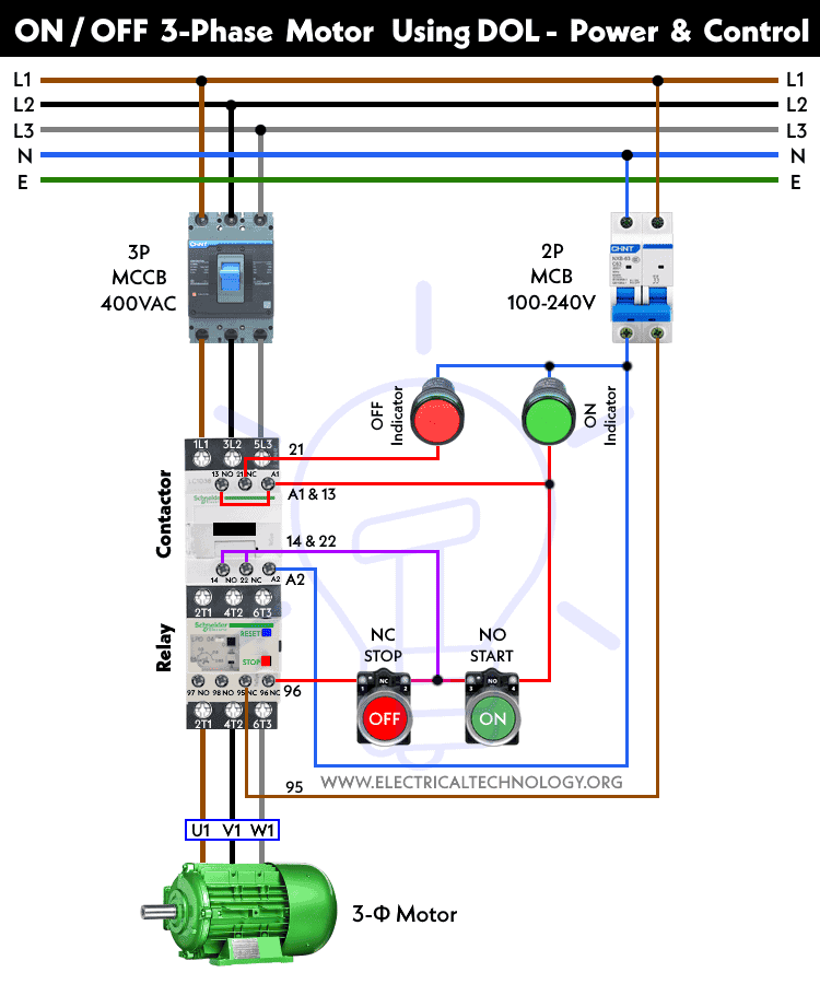
Power Diagram:

Control Diagram: 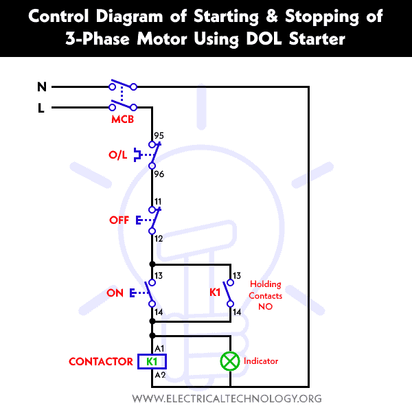
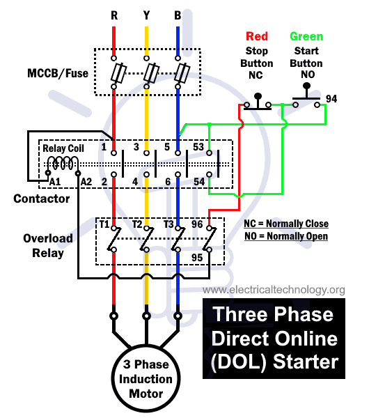
MCCB or Circuit Breaker: The R, Y and B phase are connected through MCCB to the contactors.
Magnetic Contactor: The contactor has 3 types of contacts:
1) Main Contacts: The contactor has 3 main (NO) contacts known as L1, L2 and L3.
- L1 is connected to the R phase through MCCB
- L2 is connected to the Y phase through MCCB
- L3 is connected to the B phase through MCCB
- Point 1 is connected to R-phase while point-2 is connected to overload relay T1 point.
- Point 3 is connected to Y-phase while point-4 is connected to overload relay T2 point.
- Point 5 is connected to B-phase while point-6 is connected to overload relay T3 point.
2) Auxiliary NO Contacts: the auxiliary NO contact 53 and 54 closes when the coil energizes. It is connected through the green and red push button.
- The point-53 is connected to the point-96 start button
- The point-54 is connected through the stop button.
3) Auxiliary NC Contacts: the NC contact 95 and 96 is normally closed contacts of overload relay and it opens when the current exceeds a certain limit.
- The point-96 is connected to the stop button.
Relay Coil: The relay coil points A1 and A2 are connected to the voltage supply through OLR, start button and stop button.
- The Point A1 is connected to R-phase from point 1.
- Point A2 is connected to the NC terminal of overload relay point 95.
Overload Relay: The overload relay has normally connected terminals T1, T2 and T3 that supply power to the motor.
- The T1 is connected to the point-2 of the contactor.
- The T2 is connected to the point-4 of the contactor.
- The T3 is connected to the point-6 of the contactor.
Following is the basic power and control wiring diagram of starting and stopping a three-phase motor using DOL starter.
Single Phase DOL Starter Wiring Diagram:
A single-phase DOL motor starter can be designed using the same components as shown in following diagram.
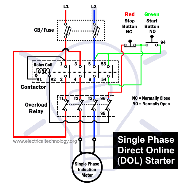
We have to use all 3 poles of the overload relay otherwise the imbalance due to the current flow in only 2 of them will cause unnecessary tripping.
Working of Direct Online Starter:
The DOL starter connects the 3 phase voltage supply i.e. R-phase, Y-phase and B-phase to the induction motor terminals.
There are two types of circuits in the DOL starter diagram given above; The control circuit and the power circuit.
The Control Circuit:
It is powered by only 2 phases of the power supply and it is responsible for starting and stopping the power supplied to the motor.
The green start button and red stop button is connected inside the control circuit. Pressing the green button for an instant starts the motor and the power is supplied when it is released. Pushing the red button stops the power supply and stops the motor.
Pressing the Start (Green) Button:
The Green button is connected to the B-phase power supply through point 5 and point 53 and it connects it to the point-A2 of the relay coil through OLR point 96-95.
Pressing the green button closes the contacts and provides the voltage supply to the relay coil that energize it. The coil moves the contactor in close position and the power is supplied to the induction motor.
Releasing the Start (Green) Button:
When the start button is released, the voltage supply to the relay coil is still maintained. The voltage supply is routed from point 54 of the contactor (close position) through OLR point 95-96.
In case of overloading, the point 95-96 of OLR opens and de-energizes the coil to open the contactors.
Pushing the Stop (Red) Button:
After releasing the start button, pushing the stop button will open its contacts and break the voltage supply to the relay coil. hence, the coil de-energize and the contactor switches to open position and stops the power supplied to the motor.
The Power Circuit:
The power circuit is responsible for providing the power supplied to the motor. Its job is to carry large amount of current required to power the motor. The switching of this circuit is controlled by the control circuit.
Principle of DOL Starter:
The Direct Online starter works on full voltage or across-the-line technique where the motor is directly connected to the full voltage supply. Since there is no voltage reduction, the starting current is very high that leads to high starting torque.
When the motor starts, it will draw a huge current usually 5 to 6 times that of its rated full speed current. The huge current draw will cause a dip in the line voltage. The gradual increase in the speed will decrease the current drawn from the lines but not below a certain speed (normally at 75%). Once the motor reaches it rated speed, the current drawn and the line voltage will return to normal.
Since the dol provides high starting current, the motor generates a high starting torque. The torque generated also depends on the rating of the motor. The load connected to the motor affects the acceleration and the time taken to reach full speed. If the load connected to the motor has high torque then the torque delivered by the motor, the motor will not accelerate. And you need to replace it with a motor having high starting torque.
Also keep in mind, the starting current may damage the windings of the motor. Thus, motors having low power rating are connected through the DOL starter.
Features , Advantages, Disadvantages, and Applications of DOL Starters
Advantages
- It is very simple to design, operate and maintain.
- It is the most cheapest and economical starter.
- It has a compact design and occupies less space.
- It provides 100% of the starting torque.
- The control circuit (green and red button) is simple and a layperson can operate it.
- Understanding and troubleshooting the system is easier.
- It connects the delta winding of the motor.
Disadvantages
- As it utilizes full voltage starting technique, the starting current is very high.
- The starting high current may damage the motor thus only low rating motors should be used.
- The high inrush current causes a voltage dip in the power lines that can be dangerous for other appliances connected in parallel.
- The high starting torque can be unnecessary in some cases.
- High starting torque causes mechanical stress reducing the life span of the motor itself.
- There is no control over the starting current and torque.
Features:
Some of the features of DOL starters are following;
- It provides high starting current.
- It provides high starting torque.
- It causes voltage dip in the power mains.
- It has the simplest controlling mechanism.
- It is suitable for low power rated motor.
Applications:
- The DOL starters are used for motor having low power ratings.
- Where the starting current does not damage the windings of the motor.
- For applications where the starting current does not cause huge dips in the line voltage.
- Direct online starters are used for small water pumps, conveyor belts, fans and compressors.
Related Posts:
- Wiring of DOL Starter for Automatic / Manual Control Using Digital Timer
- Reverse-Forward of 3-Phase Motor using DOL Starter – Wiring, Power & Control Circuit
- VFD Bypass DOL Starter – Power, Wiring and Control Circuits
- Automatic & Manual Control of Motor Using VFD & DOL Starter
- ON / OFF 3- Phase Motor Using 8-PIN Relay and DOL Starter
- ON / OFF 3- Phase Motor Using 11-PIN Relay and DOL Starter
- ON / OFF 3- Phase Motor Using 14-PIN Relay and DOL Starter
- Automatic Star-Delta Starter using Timer – Power, Control & Wiring Diagrams
- STAR-DELTA Starter Motor Starting Method Without Timer – Power & Control
- Reverse-Forward Star/Delta Starter for Three Phase Motor using Timer
- How to Start and Stop a 3-Phase Motor from Multiple Locations?
- Three Phase Slip Ring Motor Wound Rotor Starter – Control & Power Diagrams
- Even More Three Phase Motor Power & Control Wiring Diagrams


I like all information about starter. Please let me know how to save it. Also can I get this update on my email.
Thank you
You can subscribe to our mailing list. See the footer section.
Great stuff.
Thank you Soo much, I would love to learn more.
Great electrical
Please Send Full Theory of DOL Starter & Star Delta Starter With Control circuit And Power Circuit Diagram
cell phone operating bore wells circuits to 6 bores
I am interested in this technology program .
effiliz27@gmail.com
What software are using for simulating motor starter circuit