Transformer Losses – Different Types of Losses in a Transformer
Types of Energy Losses in an Electrical Transformer
An ideal transformer is characterized by zero energy losses, making it 100% efficient. However, practical transformers in real-life applications experience energy dissipation in the windings, core, and surrounding structures. Larger transformers tend to be more efficient, with distribution transformers typically operating at efficiency levels exceeding 98%.
Experimental transformers utilizing superconducting windings, which employ superconductors (a material with nearly zero losses) can achieve efficiencies of 99.85%, effectively eliminating transformer losses. However, their availability for general consumer and commercial applications may be delayed.
Related Posts: Efficiency of Transformer – All Day Efficiency & Maximum Efficiency
Power Losses in a Transformer
The different losses in the transformer are as follows
Click image to enlarge

Copper Losses (Winding Resistance)
The electric current flowing through the windings causes resistive heating of the conductors. At higher frequencies, skin effect and proximity effect create additional winding resistance and losses. The total copper losses in a transformer can be found using the following equation.
I12R1 + I22R2 = I12R 01 + I22R 02
WC = I12R1 + I22R2
Related Posts:
- Losses in a DC Motor – Power Stages & Efficiency of DC Motor
- Losses in a DC Generator – Power Stages & Efficiency of DC Generator
Core or Iron Losses
There are two types of core or iron losses in an electrical transformer.
Hysteresis Losses
Each time the magnetic field is reversed, a small amount of energy is lost due to hysteresis within the core. For a given core material, the transformer losses are proportional to the frequency, and is a function of the peak flux density to which it is subjected.
We can find Hysteresis losses by this formula.
Wh = Kη Bmax1.6 f v … Watts
Where:
- Wh = Hysteresis losses in Watts
- Kη = Coefficient of eddy current
- Bmax = Max. value of flux density in wb/m2
- f = Supply frequency in Herts
- v = Volume of the magnetic material in m3
Related Posts:
- Losses in a induction Motor – Power Stages in Induction Motors
- Losses in Alternator – Power Stages & Efficiency of Synchronous Generator
Eddy Current Losses
Ferromagnetic materials are also good conductors, and a core made from such a material also constitutes a single short-circuited turn throughout its entire length. Eddy currents therefore circulate within the core in a plane normal to the flux, and are responsible for resistive heating of the core material.
The eddy current loss is a complex function of the square of supply frequency and inverse square of the material thickness. Eddy current losses can be reduced by making the core of a stack of plates electrically insulated from each other, rather than a solid block; all transformers operating at low frequencies using laminated or similar cores.
We can find Eddy currents losses by the following formula.
We = P Bmax2 f2 t2 … Watts
We = Ke Bmax2 f2 t2 v … Watts
Where:
- We = Eddy current losses in Watts
- Ke = Coefficient of eddy current
- Bmax = Maximum value of flux density in wb/m2
- f = Supply frequency in Herts
- T = Thickness of lamination in meters
- v = Volume of the magnetic material in m3
Related Posts:
- Losses in Synchronous Motor – Power Stages & Efficiency of Synchronous Motors
- Losses in Electrical Machines – Formulas and Equations
Stray Losses (Leakage Flux)
Leakage inductance is by itself largely lossless, since energy supplied to its magnetic fields is returned to the supply with the next half-cycle. However, any leakage flux that intercepts nearby conductive materials such as the transformer’s support structure will give rise to eddy currents and be converted to heat. There are also radiative losses due to the oscillating magnetic field, but these are usually small and negligible.
Dielectric Loss
In the solid insulation or transformer oil i.e. insulation material of the transformer, dielectric loss occurs when the solid insulation gets damaged or the oil gets deteriorated or its quality decreases over the time. Hence, the overall efficiency of the transformer may be affected due to this loss.
- Related Post: Why Transformer Rated In kVA, Not in KW?
Other Losses
Magnetostriction Losses
Magnetic flux in a ferromagnetic material, such as the core, causes it to physically expand and contract slightly with each cycle of the magnetic field, an effect known as magnetostriction. This produces the buzzing sound commonly associated with transformers, and can cause losses due to frictional heating.
Mechanical Losses
In addition to magnetostriction, the alternating magnetic field causes fluctuating forces between the primary and secondary windings. These incite vibrations within nearby metalwork, adding to the buzzing noise, and consuming a small amount of power.
Related Posts:
- EMF Equation of a Transformer
- Equivalent Circuit of Electrical Transformer
- How to Size a Transformer in kVA? Rating of a Transformer? Calculator
- Parallel Operation of Single-Phase & Three-Phase Transformers
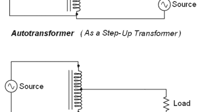
- Autotransformer – Its Types, Operation, Advantages and Applications
- Transformer Performance & Electrical Parameters
- Power Transformer Protection and Faults
- Transformers Insulation Materials in Oil-Immersed & Dry Type T/F
- Transformers Fire Protection System – Causes, Types & Requirements
- Transformer Phasing: The Dot Notation and Dot Convention
- Electrical Transformer Symbols – Single Line Transformer Symbols
- Which Transformer is More Efficient When Operates on 50Hz or 60Hz?
- Current Transformers (CT) – Types, Characteristic & Applications
- Potential Transformer (PT)? Types & Working of Voltage Transformers
- Autotransformer – Types, Operation, Advantages and Applications
- What is an Isolation Transformer? Construction, Working and Applications
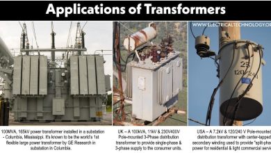
- Uses and Application of Transformer


awesome explaination
can u calculate losses in 750 KVA transformer. we using 20 hrs. every day load on average 450 amps.
input volt is 33000 high tension line voltage /out put is 415 volt 50 HZ. ALSO calculate being make unit consumed during losses when no load on SUNDAY /holidays. POWER FACTOR IS ALWAYS .99/UNITY.
KINDLY we request can u send formula how do i calculate losses ?.
Dear Sir,
pl. provide me the list of No load loss and full load loss of all capacities of distribution as well as power transformers of all possible voltage ration. I shall be really grateful for the same.
Dear Sir,
can anybody tell about the % transformation losses in power transformers i.e. 66/11 KV of 15 and 20 MVA ratings and other voltage ration also. .
Would like to have technical informations