How to Control One Lamp From Three Different Places?
3-Way & 4-Way Switching Connections – Electrical Wiring Diagrams
What is 2-Way & 3-Way Switching Circuits?
Three-way switching or (Four-way circuits in the US) connection is used to control electrical appliances and equipment like fan, lighting points etc. from more than two places. The most common applications of this configuration is staircase wiring, hallway & corridor wiring, hostel wiring, hospital wiring, tunnel wiring, godown wiring etc. where a light bulb is controlled from two, three or even more places for ON and OFF operations.
Two Way or Three Way Switch? Three Way Switch or Four Way Switch: “4-way” is the North American (USA) term used for crossover switch. While mentioning the same thing, most English-speaking countries (UK/EU) call them “3-way” or intermediate switch. The term for the pair of wires connecting the two switches also varies: “strappers” to the British and “travelers” to the US.
Please ignore if we mention it 3-Way or 4-Way switch as they are interchange words representing the same thing.
Related Wiring Diagrams:
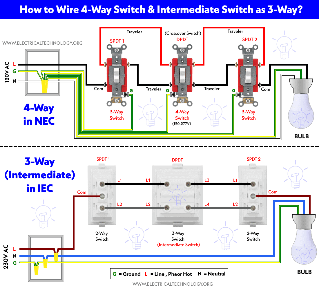
- How to Wire 4-Way Switch (NEC) & Intermediate Switch as 3-Way (IEC)?
- How to Wire Single Pole, Single Throw (SPST) as 2-Way & 1-Way Switch? IEC & NEC
- How to Wire Single Pole, Double Throw (SPDT) as 3-Way & 2-Way Switch? IEC & NEC
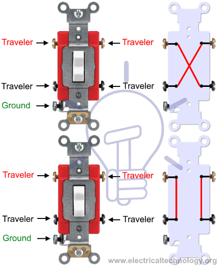
Construction & Working of a 3-Way & 4-Way Switch
The 3-Way switch is also known as Single Pole Double Through (SPDT). The basic construction and working principle of 3-way switch is illustrated in (fig 1) below.

Related Posts:
For this kind of wiring installation, you will have the following requirements.
- 1 No of 4-Way Switch (Intermediate as 3-Way in IEC)
- 2 Nos of 3-Way Switches (Two-Way Switches in the NEC)
- 1 No of Light Bulb
- Wires and cables as needed.
How to Control One Lamp From Three Places?
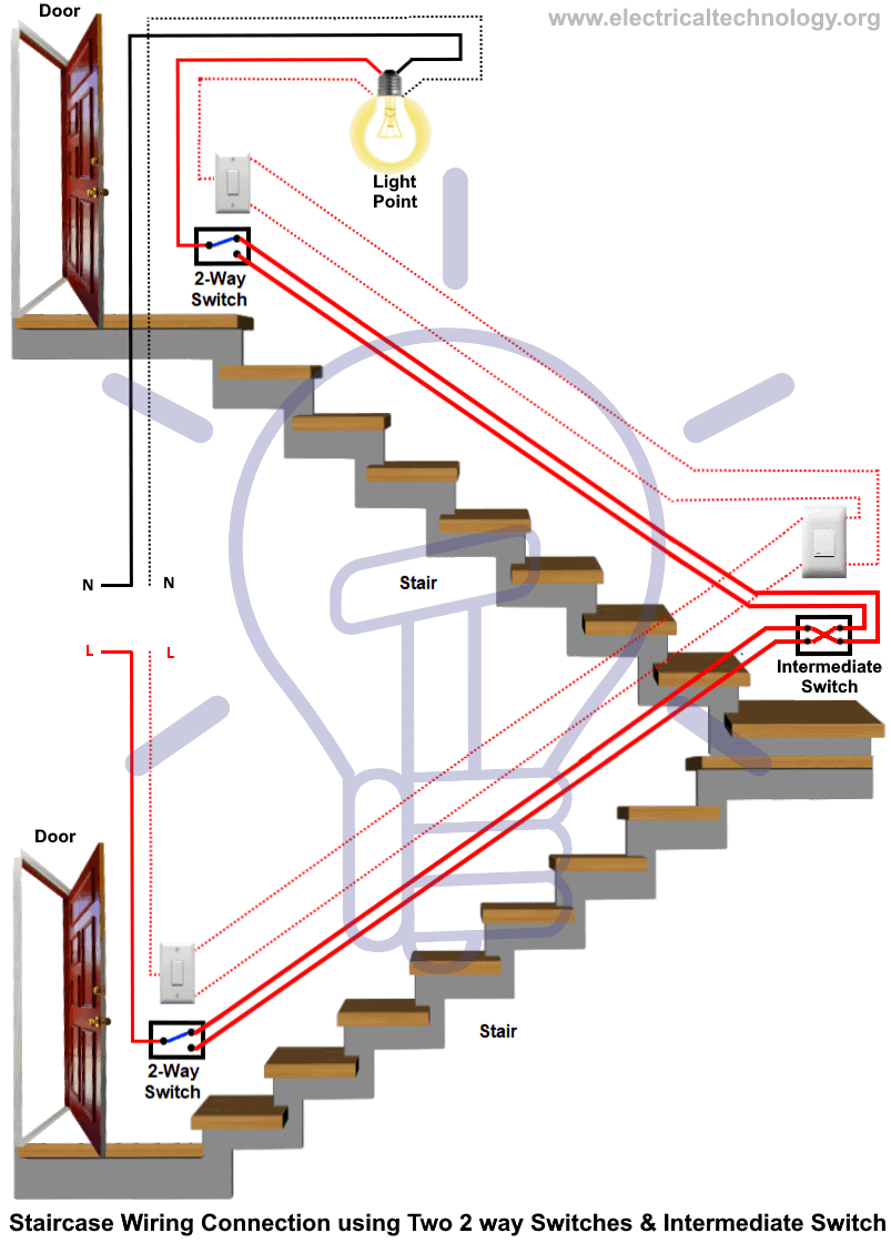
In fig 4, the wiring diagram shows how to control a light point from three different places by using two 2-way switches and an intermediate switch.

Fig 5 shows the same connection to control a light point from three places by using different symbols.

Related Posts:
Three Way Switching to Control Light from Three Places in Staircase
The following wiring diagram shows how to control a light bulb from three different places using two 2-way (or 3-way) switches and an intermediate switch or 4-way switch.
The following wiring diagram shows how to control a light bulb from three locations according to NEC and IEC.
Click image to enlarge
Related Posts:
- How to Control One Lamp From Two Different Locations?
- How to Control One Light Bulb from Five or Six Different Places? – IEC & NEC?
Applications of 2-Way & Three Way Switching
- It is used to control electrical equipment and appliances from two different locations
- It is also used in staircase wiring connections where a light point can be controlled from two or more different places.
- It is used in large area premises, rooms, halls having two or more entry and exit points.
- The main purpose of 2-way & 3-way switching is to control an electrical appliance, device or equipment, especially light points from two places.
Related Electrical Wiring Installations tutorials:
- How to Wire an Outlet Receptacle? Socket Outlet Wiring Diagrams
- How to Find the Number of Outlets on a Single Circuit Breaker?
- How to Find Voltage & Ampere Rating of Switch, Plug, Outlet & Receptacle
- How to Wire a Pilot Light Switch? Wiring of 2 & 3 Way Neon Light Switches
- How to Wire Combo Switch and Outlet? – Switch/Outlet Combo Wiring Diagrams
- How to Wire an AFCI Combo Switch – AFCI Switch Wiring Diagrams
- How to Wire GFCI Combo Switch and Outlet – GFCI Switch/Outlet Wiring Diagrams
- How to Control Water Heater using Switches?
- How to Wire a Ceiling Fan? Dimmer Switch and Remote Control Wiring
- How to Wire Auto & Manual Changeover & Transfer Switch – (1 & 3 Phase)
- Automatic Bathroom Light Switch Circuit Diagram and Operation
- Staircase Wiring Circuit Diagram – How to Control a Lamp from 2 Places by 2-Way Switches?
- How to Control a Lamp by a Single Way or One-Way Switch?
- How to control each lamp by separately switch in parallel lighting circuit?
- Corridor Wiring Circuit Diagram – Hallway Wiring using 2-Way Switches
- Hospital Wiring Circuit for Light Control using Switches
- Hostel Wiring Circuit Diagram and Working
- Godown Wiring Diagram -Tunnel Wiring Circuit and Working
- Tunnel Wiring Circuit Diagram for Light Control using Switches
- How to Wire a UK 3-Pin Plug? Wiring a BS1363 Plug
- How to Wire a UK 3-Pin Socket Outlet? Wiring a BS1363 Socket
- How to Wire a Twin 3-Pin Socket Outlet? Wiring 2-Gang Socket
- How to Wire Combo Switch and Outlet? – Switch/Outlet Combo Wiring Diagrams
- Switch and Push Button Symbols
- Basic Electrical Wiring Diagrams


thanks
Most Welcome Dear Imran
Thanks for sharing
PROVIDE FOR ME A VIDEO OF SOME WIRING AN INTERMEDIATE CIRCUIT CONTROLLING TWO LAMP FROM 3 POSITION ON A PANEL
how to control for lamp controlled by four intermidiate switch
that a good one
haloo sir 3 lamps ko 2 switches par control karna he
haloo sir 3 lamps ko 2 switches par control karna he is ka tareeqa batayen plzzz
sir how i cheak a mosfe by a digital multi mitter?
Not possible to get definitive results with a multimeter.
Gate to source and gate to drain should read open circuit either polarity. That indicates either a good MOSFET, or one that is dead with the gate blown open. The only informative reading is when you see some resistance. Then you have a bad MOSFET, but you can’t make those readings with the device in circuit – or you likely will just be getting a reading from some other circuit elements.
Drain to source will read open for an enhancement mode MOSFET but some value of resistance depending on the construction of the device for a depletion mode MOSFET.
Some MOSFETS have an internal diode structure from drain to source so your reading will be polarity dependent.
Unless you know what kind of MOSFET you have, multimeter testing is pretty pointless.
Why extra Phase wire and not a Neutral ?