Voltage Divider Rule Calculator – VDR Examples & Applications
Voltage Divider Circuit – Voltage Divider Rule “VDR” Calculator, Examples and Applications
Voltage Divider Circuit
A Voltage Divider Circuit uses resistors to reduce voltage, and is the most common circuit used in electronics. Voltage Divider can be used to do lot of things like to create a volume control circuit or generate reference voltage and much more. Voltage Divider are also used in analog circuits to get variable voltage outputs. This circuit works fine with both AC and DC input voltage, in this input voltage value is converted into another voltage value.
Note: The Output voltage value of a voltage divider circuit is always be less than the input voltage value.
In Voltage Divider Circuit the output voltage is always depends upon the proportion of the amount of resistance. Like if you have taken two equal value of resistor you will receive exactly half of the input voltage at output.
An electrical equivalent circuit of voltage divider is given below:
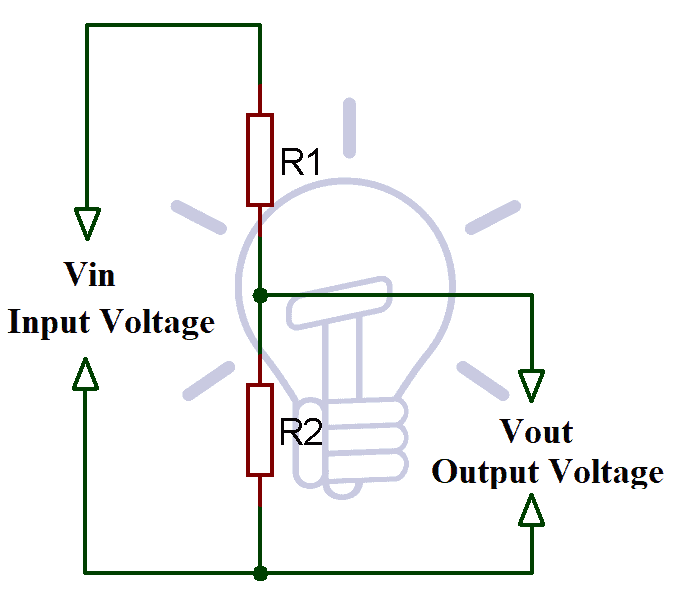
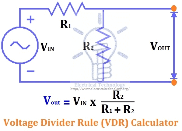
As you can see the voltage divider circuit consists of two resistors connected in series with a voltage tap between them. And, the input voltage is applied across the resistor R1 and R2. Therefore, we can observe that the output voltage is the voltage drop across the resistor R2. The voltage across R1 and R2 will be equal to the input voltage value applied to the voltage divider circuit.
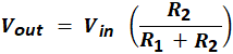
The formula of Voltage Divider Equation for finding the value of output voltage will be expressed as:
Where,
- Vin = Input Voltage
- Vout = Output Voltage
- R1 = Resistor connected to source
- R2 = Resistor connected to ground
Related Posts:
- Current Divider Rule (CDR) – Solved Examples for AC and DC Circuits
- Voltage Divider Rule (VDR) – Solved Examples for AC and DC Circuits
Proof of Voltage Divider Formula
Now, we will explain you the mathematical explanation of the above formula. So, according to the Ohm’s Law, the potential difference across an ideal conductor will be equal to the current flowing through it.
V = IR
Where, V, I and R are Voltage, Current and Resistance respectively.
So, the voltage across the above circuit will be equal to the product of the current in the circuit and the total resistance.
The total resistance of the circuit in a voltage divider circuit is
RT = R1 + R2
Vin = IRT
Vin = I (R1 +R2)
On solving,
I = Vin / (R1 +R2)
Here, the output voltage is taken across the resistance R2, so Vout will be expressed as:
Vout = IR2
Now, put the value of I from the above equation,
Now, we will explain you how a voltage divider works, and how you can even find the resistance value to get the desired voltage value.
Voltage Divider Circuit – Example
As shown above, a voltage divider circuit is consists of two resistor (R1 and R2) and the output will be taken across the resistor R2. The only thing you need to take care of is the power rating of the resistors. Because if we will not select the proper power rating of resistor then resistors will overheat or may burn also. You can calculate the power rating if you know the value of I (based on load), by using the power law equation (P = VI).
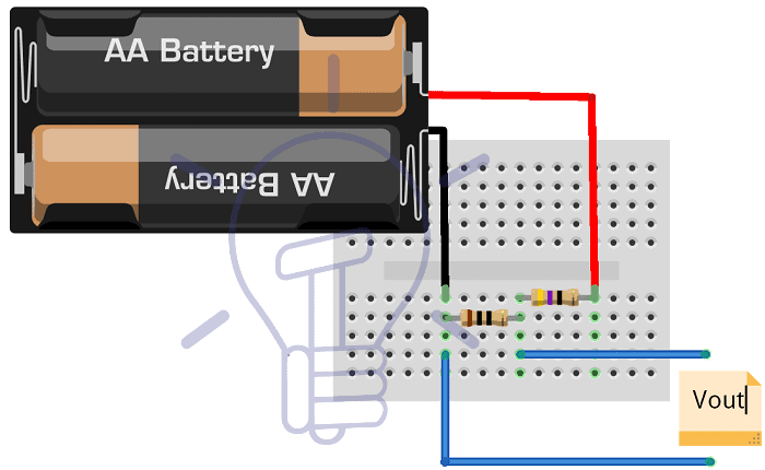
Things you need to develop a voltage divider circuit are:
- Resistors (10kk, 47k ohms)
- Input Supply (9V)
- Breadboard
- Multi-meter (to measure)
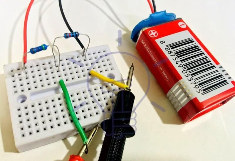
Now, we will demonstrate you the output of the voltage divider circuit practically and theoretically.
Here, in this circuit we have connected 9V input voltage and resistors R1 & R2 (47k and 10k respectively). After taking the output of voltage divider circuit from multi-meter we are getting 1.49V.

Now, we will calculate the output voltage of the above circuit theoretically,
Here, Vin = 9V, R1= 47k Ω and R2 = 10k Ω
So, by using the Voltage Divider Equation
We have,
Vout = (9 × 10) / (47+10)
Vout = 1.5789
Hence, you can see the difference between the practical and theoretical value, because of the battery voltage is not exactly 9V. Also, you can find the value of resistor according to your desired output voltage by using the above formula.
Related Posts:
Voltage Divider Rule Calculator
You can also use the Voltage Divider Calculator for calculating the voltage divider output or even resistors value according to your desired input and output values.
Enter any three of the following values and click on calculate button. Result will display the required value.
Note: Formulas and equations for this calculator is given below ( after calculator). Also do not forget to share with and suggest to your friends. Also, if you want to see other electrical and electronics calculators live on our blog, then please mention it in below comment box. thanks.
Formula for VDR Calculator
VOUT = VIN x (R2 / (R1 + R2))
Where
- VIN = Input Supply voltage
- R1+ R2 = Resistors values
- VOUT = Output Voltage
Related Posts:
Advantages & Disadvantages of Voltage Divider Circuit
There are some advantages and disadvantages of the voltage divider circuit which are mentioned below:
Advantages of Voltage Divider Circuit
- Easy and convenient method for measuring the high voltage (upto 100KV)
- Simple method for voltage level shifting.
- Helps in setting the output voltage of the regulators (like LM317)
Disadvantages of Voltage Divider Circuit
- Not efficient to use for power supplies.
- Resistors of voltage dividers introduces small power loss.
- Sometimes voltmeter resistance affect the ratio of the resistors.
Application of Voltage Divider Circuit
Now, as we know that there are number of application of the voltage divider circuit. Some of the applications are mentioned below:
Potentiometers
A potentiometer is a three terminal variable resistor, using this you can design an adjustable voltage divider. If you will use only two pins of potentiometer (one should be adjustable pin), it will work as rheostat. But if you are using all the terminals, and taking the output through the adjustable pin, here it works as a voltage divider.
Similarly, potentiometers have many applications, it is also used in joysticks and to create reference voltage.
Reading Resistive Sensors
Most of the sensors are simply resistive devices, like as a LDR (Light Dependent Resistor) which vary its resistance according to the intensity of light falls over it. Similar to LDR there are number of sensors which does the same with respect to resistance like flex sensor, force sensor and thermistors.
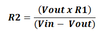
Here, voltage divider circuit is used for calculating the resistance of the sensor. By replacing the resistor R2 (as per the circuit diagram) with the resistive sensor, we can calculate its resistance by using the below formula
R2 = (Vout x R1) / (Vin – Vout)
Where, R2 is the Resistive Sensor
Level Shifting
While interfacing with a microcontroller, not all sensors works on a standard voltage value (5V), there are number of sensors which operates at relatively low-voltage. Here, the problem of level shifting occurs, so to drop down the interfacing voltage we use voltage divider circuits to get the determined voltage.
High Voltage Measurement
When it is hard to measure High Voltage value, the voltage divider again comes in application. A voltage divider scale down a very high voltage so it gets easy to measure via voltmeters.
Simply, the high voltage is applied to the input of the voltage divider, and its output (set to be lower than voltmeter max. range) measured by the voltmeter. There voltmeters have specifically designed probes with high voltage resistor to tolerate the coming high input voltage to produce accurate results in measuring the high voltage. We can measure up to 100KV by using this application of voltage divider circuit. The capacitor divider circuit are used for measuring more than 100KV of voltage value.
Related Post: Parallel Resistor Calculator
Voltage Divider for Variable Power Supply
Let’s assume, we have 9V battery and you need an output voltage value between 1V to 8V. As above mentioned, by adjusting the potentiometer connected with a 9V battery, we are able to get an output voltage between 1V to 8V.
Connect the battery according as per the below circuit diagram:
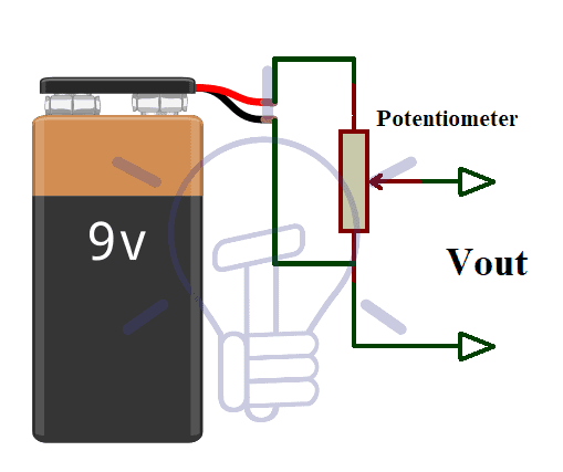
Note: Using a Voltage Divider Circuit for power supply may cause Loading Effect. Also, it is not an efficient way to control the power voltage, as power dissipates in Resistor R1 with no useful gain.
So, this is how a potentiometer will be able to deliver variable output voltage.
Now, suppose you need a fixed supply voltage for any particular device or controller, what you will do? For that you need exact value of resistor instead of potentiometer to get the desired output.
Like we need 5V output from a 9V battery (Neglecting the current to the load resistor)
By rearranging the voltage divider formula you can find the values of the resistor you need for any specific output value.
First, you have to choose you input voltage value and any one resistor value (R1 or R2). So, if you fixed the value of R1 and now you need to find the value of the R2 use the below formula:
If you have fixed the value of R2 and you need to find the value of R1 then use the below mentioned formula:

Here, I need 5V of output from 9V input voltage,
So,
Vin = 9V
Vout = 5V
R1 = 8k (fixed resistor)
R2 = ?
By using the formula for R2
We have,
R2 = (5 x 8) / (9 – 5)
R2 = 40 / 4
R2 = 10
Hence, if you take R2 of 10k and R1 of 8k with input voltage of 9V, you output voltage will be equal to 5V volt.
Related Posts:
- Electrical Wire & Cable Size Calculator (Copper & Aluminum)
- Wire & Cable Size Calculator in AWG
- Resistor Color Code Calculators – 3, 4, 5 & 6 Bands
- Standard Wire Gauge “SWG” Calculator – SWG Size Chart & Table
- American Wire Gauge “AWG” Calculator – AWG Size Chart & Table
- Power Factor Correction Calculator – How to Find P.F Capacitor in µF & kVAR?
- Capacitor Bank in kVAR & µF Calculator for Power Factor Correction
- Electrical & Electronics Engineering Calculators


Can u please show me how to assemble a main distribution board nd house wirings