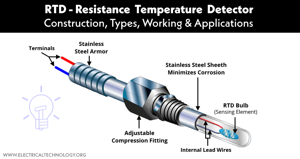
RTD – Resistance Temperature Detector: Construction, Types, Working & Applications
Resistance Temperature Detector or RTD: Construction, Working, Types, Advantages, Disadvantages & Applications
Temperature plays a vital role in the performance of any electrical and electronic device. There are various sensors used to monitor the temperature such as a thermistor, thermocouple, RTD (resistance temperature detector), etc. In this article, we are going to discuss RTD.
As we know that conductors experience change in their electrical resistance when their temperature changes. The RTD uses this property to translate the temperature into the proportional electrical resistance which can be easily measured.
What is RTD “Resistance Temperature Detector”?
RTD or resistance temperature detector is an electrical sensor used to measure the temperature of the environment by measuring the change in electrical resistance of a metallic wire.
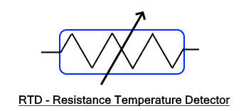
The metallic wire is referred to as the temperature sensor whose resistance varies with the temperature. The resistance is measured using any other device to translate into temperature. It has high accuracy and linear characteristics as compared to other temperature sensors.
Related Posts:
Working Principle of Resistance Temperature Detector
The RTD device works on the principle that the resistance of a conductor changes due to a change in temperature. As we know the resistance of a given conductor having length “l” & area “a” is given by;
R = ρ l / a
Where
- R = Resistance of the wire
- ρ = Resistivity of the material
- l = length of wire
- a = cross-sectional area of the wire
ρ is the resistivity of the material which is measured in ohm-cm. It depends on the type of material as well as its temperature. Since the length & the area of the wire remains constant throughout RTD operation, the resistance becomes the function of only temperature. Therefore the resistance of a metal at a given temperature ’t’ is given by
Rt = Ro (1 + αt)
Where
- Rt = Resistance at temperature t
- Ro = Resistance at a reference temperature
- α = coefficient of temperature
The resistance value depends on α, the coefficient of temperature. It is different for different metals. Therefore such metals are best suited for the RTD element that has the highest α value.
Construction of RTD
An RTD or resistance temperature detector is made by wounding the resistive material around a mica base. The material used is drawn into a fine wire to form the elements of the RTD. The wire is wounded in helical shape & its both terminals are brought out at the same side. The element is protected by a stainless steel case or sheath. There is an insulator between the element and the outer sheath.
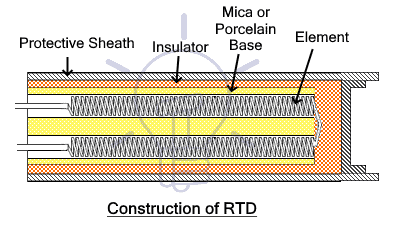
The element is designed in a helical shape to reduce the effects due to tension on it. As we know that the resistance of a wire depends on the temperature as well as the length of the wire. Due to thermal expansion, the wire length increase with temperature which also affects the resistance of the elements. It causes an error in the reading because we want the only temperature to change the resistance & not the physical strain on the wire. Therefore the element is designed in a helical shape.
The outer protective sheath is made of Inconel, an alloy made of nickel, iron & chromium. It has excellent corrosion resistive properties to protect the inner element from harsh environments. It is an excellent heat conductor that quickly reaches the surrounding temperature and passes it to the element.
Types of RTDs based on Construction
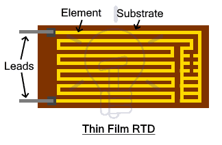
Thin film RTD
Thin film RTD element is made by depositing a thin layer of the temperature sensitive material such as nickel, platinum & copper on the insulating substrate. The material is carved into a pattern to meet the required temperature. The terminals are then attached to the element & a protective sheath covers the element to protect it.
Wire wound RTD
The element of wire wound RTD is made of a helical coil. It is the most commonly used design type. The wire wound element can be constructed in two types.
- The most common design type is that the wound element is packaged inside the insulating as well as the protective sheath. The insulating material ceramic is used.
- The other type has the element wound around an insulating core with an additional insulating material used for covering the element. This structure is used for special purpose applications.
Wire Configuration
The RTD must be connected to some sort of resistance measuring circuit or device in order to measure the temperature. Since the temperature reading depends on the resistance of the element, any unwanted resistance such as lead & connection resistance adds into the reading to cause an error. To compensate for this error, different types of wire configurations are being used such as 2-wire, 3-wire, 4-wire & 2 wire with compensation loop.
2 Wire
In 2-wire configuration system, a single lead wire is connected with both ends of the RTD element. The lead wires are used to connect the RTD element with the measuring device. Since the device measures the total resistance of the circuit that also includes the resistance of both lead wires 1 & 2, the temperature reading includes errors due to it. The reading will be always higher than the actual temperature.
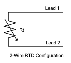 It is the simplest configuration being used. Due to the said disadvantage mentioned above, it is used in applications where high accuracy is not required.
To eliminate the lead resistance, the following configurations are used.
3 Wire
The 3-wire configuration includes a total of 3 lead wires connected between the RTD element and the measuring device. Two lead wires are used to connect one side of the RTD element to the measuring device while a single lead wire is used to connect other side. The third wire helps in compensating for the error due to lead wire resistance. It is the most commonly used RTD configuration commercially due to its quick and accurate readings.
 The length of the 3 lead wires and the type of material used are kept the same. The lead 1 & 2 are used for measuring the total resistance i.e. the resistance of the RTD element and the lead 1 & 2 as well. Whereas lead 1 & 3 are used to measure the resistance of only leads. Thus the lead resistance is subtracted from the total resistance to have more accurate temperature readings.
But the readings can only be accurate if all three leads have equal resistance. Otherwise, there might be some errors. To further eliminate this error down to zero; 4-wire configuration is used.
4 Wire
The 4-wire RTD configuration has two lead wires connected at each side of the RTD element thus making a total of 4 lead wire connections. It has the most accurate temperature readings but its installation is costly and the response time is fairly slow. They are used in labs where accuracy is of the utmost importance.
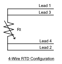 The lead wires are used to are marked as 1, 2, 3 & 4 as shown in the figure. The measuring device connects all four lead wires. The outer lead wires 1 & 2 are used to pass constant current through the RTD element while the inner lead wires 2 & 3 are used to measure the voltage across the element. The voltage readings are used to calculate the resistance of the element using Ohm’s law V = IR.
2 Wire Configuration with Compensation Loop
 In this configuration, there is an extra closed loop of the lead wires called the compensation loop. This separate loop is used to measure the resistance of the lead wires. Therefore, the material and length of the loop are same as that of the other two lead wires. But this method is rarely used.
Types of Material used in RTD Construction
The RTD element consists of a pure metal whose electrical resistance is directly proportional to the change in temperature i.e. their resistance increases with an increase in temperature and vice versa. The resistance is converted into a voltage signal that represents the proportional temperature value.
Almost every conductor shows a change in resistance as its temperature changes. However, they are not that significant due to their low temperature coefficient. But there are certain metals that show properties that offer best performance and linear characteristics. They must possess the following characteristics to be used as an RTD element.
- It must have high temperature coefficient to provide high resistance change per degree of temperature.
- It must have a linear relationship between temperature and resistance.
- It must provide repeatability i.e. its resistance must not change for the same temperature over a span of time.
- It must be durable.
- It must be able to withstand the temperature that is being measured.
 The element of RTD is usually made of metals having positive temperature coefficients such as platinum, nickel, copper, or nickel alloy. These materials show stability as well as high temperature coefficient.
Copper
The copper shows linear characteristics with a relatively high temperature coefficient i.e. high resistance change per degree of temperature. However, their operating temperature range is low with low accuracy. It is cheaper than other elements, therefore, it is used in applications where high accuracy & high temperature range is not required such as in motor windings, etc.
Nickel
Nickel shows the highest temperature coefficient of all RTD elements. However, the relation between temperature and resistance is less linear. It results in lower accuracy. Its temperature range is wider than copper but lower than platinum. Since it has lower accuracy, it is used due to its cheaper price as compared to platinum.
Platinum
Platinum shows the most linear characteristics of all three. It provides operation over a wide range of temperatures with high accuracy and repeatability. It has a high temperature coefficient but is expensive as compared to other RTD elements. The platinum RTD elements are used more commonly in industrial applications.
Related Post:
Advantages & Disadvantages of RTD
Advantages
Here are some advantages of RTD
- It can operate at a wide range of temperatures.
- Its readings are consistent and highly repeatable at high temperature.
- They are resistant to corrosion & best for extreme environments.
- It has more linear characteristics.
- It has excellent accuracy over a wide range of temperatures.
- It is stable & has a longer life span at high temperature measurement.
- The RTD is constructed, installed, and replaced easily.
- It can measure differential temperature.
- They are suitable for monitoring remote areas.
Disadvantages
Here are some disadvantages of RTD
- It requires a current source.
- Its accuracy depends on the battery’s health.
- Heat is generated due to I2R losses in the element also known as self-heating which inflicts error in the measurement thus affecting the accuracy.
- It has a large size, therefore, unable to sense temperature at small points.
- It is affected by physical shock and vibration.
- It has a limited temperature operating range as compared to thermocouple.
- It has a higher initial cost as compared to thermocouple.
- It has complex operating circuitry or signal conditioning unit.
- It requires an external circuit to operate such as a bridge circuit with a power supply.
- It has low sensitivity & slower response time.
Applications of RTD’s
RTD is generally used for continuous monitoring of temperature in various applications. Some of these applications are given below.
- It is used in applications where temperature control is important.
- It is used in remote areas where it is difficult to get access.
- It is used to measure the temperature of the engine & the air intake in automotive.
- In different industrial processes such as food handling and manufacturing, it is used to monitor the temperature.
- In different power electronics, medical & military electronics use RTD.
- It is also used in multiple communication and instrumentation for temperature measurement.
Related Posts:
- What is a Transducer? Types of Transducers and Applications
- LVDT: Linear Variable Differential Transformer and Inductive Sensors
- Capacitive Sensor and Transducer and Its Applications
- What is Piezoelectric Sensor? Construction, Working and Applications
- Types of Resistive Sensors and Transducer, Potentiometer and Strain Gauge
- What is a Thermistor? Types of Thermistors and Applications
- Thermocouple – Types, Construction, Working and Applications