How to Wire a Fire Alarm System with Detectors ? – Wiring Installation Diagrams
What is a Fire Alarm System?
A fire alarm system is a mechanism of different interconnected devises and components used to alert us in case of emergency especially fire to protect the staff and general public by taking appropriate actions.
Fire alarm system is the combination of different components such as smoke detector, heat detector, carbon monoxide detector, multi sensor detector, call points, sounders, bells, relay module, repeater, annunciator, fire control panel and other related and optional security devices designed for fire alarm control system.
Like a CPU (central processing unit) in a computer system, the fire alarm control panel is the brain of fire alarm system which sends a status indication and notification to the connected detectors and sounders in case of manual or automatic operation.
Fire alarm systems are wired in industrial factories, offices, public buildings and nowadays even in homes. Different types of fire alarm system such as conventional, addressable, intelligent and smart wireless designs are used for the same purpose i.e. in case of emergency, the sounders will operate to warn the people around to evocative via general or emergency exit. The main purpose of a fire alarm system is to protect the wealth, health and life of individual or society.
A smart fire control system is also connected to the fire brigade and related emergency personnel through remote control via control panel.
The following tutorial will explain the different fire alarm system and their wiring diagrams and connection
Types of Fire Alarm Detectors
There are multiple detectors used in a fire alarm system including the basic call point (manual break glass unit) and smart multi sensors detector. The fire detection devices can be categorized as follow.
- Smoke Detector
- Heat Detector
- Multi Sensors Detector
- Carbon Monoxide Detector
- Manual Call Point
Smoke Detectors
Smoke detectors can be categorized as follow based on design and working principles.
- Ionization Smoke Detectors
- Light Scattering Smoke Detectors
- Light Obscuring Smoke Detectors
Ionization Smoke Detector
Ionization Smoke detectors work based on lowering the current flow through the inside chamber due to ionization which leads to initiate the alarm.
There are two chambers in a typical ionization smoke detector. The first chamber is used to compensate the changes in ambient temperature, pressure or humidity while, there are alpha particles (radioactive material) in second chamber which is used to ionize the passing air in the chamber where current flows between two electrodes. In case of fire when smoke enters the chamber, the current flow between two electrodes reduced due to ionize air. The drop in the current flow is used to trigger the sounder and alarm circuit.
Light Scattering Smoke Detector
Light scattering smoke detectors work based on Tindal effect (it is an effect of scattering of light when light beam passes through a colloid (a homogeneous (a substance that is consistent or uniform throughout its volume) mixture in which the dispersed particles do not settle out).
A light source and a photocell are fixed in a darkened chamber where direct light doesn’t fall on the surface of photocell.
When smoke enters the chamber, it distorts the chamber environment which leads to scatter the light and fall on the surface of photocell. This effect is used to imitate and trigger the alarm system.
Light Obscuring Smoke Detector
Light obscuring smoke detectors work based on measuring the amount of light falling on the surface of a photocell.
Inside the light obscuring smoke detector chamber, the light source and photocell are positioned at fixed distance. When the smoke interferes the light beam from the light source to the photocell, it measures the amount of light it receives from the light source. This variation in the output receiving by photocell is used to trigger the alarm circuit.
Heat Detectors
Hear detectors work based on the rate of change in temperature or a specific value of a fixed temperature rate.
In case of heat rise to the pre-set value, the eutectic alloy inside the heat detector (which is heat sensitive to the specific temperature) turns from a solid to the liquid. The process is same like the working of a fuse where fuse element melts when needed. The same process will trigger the alarm circuit in case fire.
Carbon Monoxide Detectors
Carbon monoxide detector is also known as CO detector. It is an electronic device which contains on different types of sensors used to measure and sense the amount of carbon monoxide gas in the air. When the level of carbon monoxide (it is a poisonous gas produced by combustion) crosses the specified limit, it indicates and triggers the fire alarm system. The electrochemical cell inside the carbon monoxide detector only sense and measure the amount of CO gas and not other combustion gases like smoke etc.
Keep in mind that the carbon monoxide detectors designed for fire alarm system are more sensitive with quick response as compared to the CO detectors used in homes for CO protection in case of incomplete combustion process in appliances such as boilers etc.
Multi-Sensor Detectors
The multi sensor detector (also known as multi-criteria alarm) is a sensitive device which combines the input signal from both heat and optical sensors and used for wide range of fires with lower rate of unwanted false alarms.
It can be used to detect optical, heat, CO and fires as it has the ability to detects multiple signals and send the identification value to the control panel for further appropriate action. Hence, an intelligent multi-sensors alarm can be used for accurate and verified correct operation.
Manual Call Points
A fire alarm manual call point (also known as break glass point) is a device which is used to trigger the alarm circuit by breaking the glass and pressing a frangible element in case of emergency or fire.
Call points are installed at 1.4 meter above the floor level for ease access in case of emergency. The maximum length between two call points is 30 meters and installed on the entry floor landing of stair cases, exit routes and at all exits to the open air.
Types of Fire Alarm Systems with Wiring Diagrams
Following are the different types of fire alarm systems with wiring and connection diagrams.
- Basic Fire Alarm in Home
- Conventional Fire Alarm System
- Addressable Fire Alarm System
- Intelligent Fire Alarm System
- Wireless Fire Alarm System
Lets discus each one in details as follow:
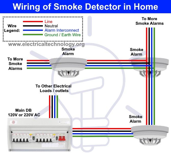
Basic Fire Alarm in Home
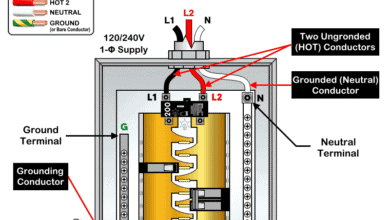
This is the basic fire alarm system used in household wiring. A smoke or heat detector can be installed to the existing or new home wiring. in our basic wiring diagram, a single or multiple heat and smoke detectors are installed in the home by connecting the live (line or hot), neutral, ground and an interconnected wire to the alarm. The main supply is 120V AC (in US) and 230V AC (in EU). The detectors can be directly connected to the DB (distribution board) or an existing wiring like outlet. After installation, put the battery and switch on the main breaker to check if it works properly.
Wiring Diagram of Heat Detector in Home (AC)
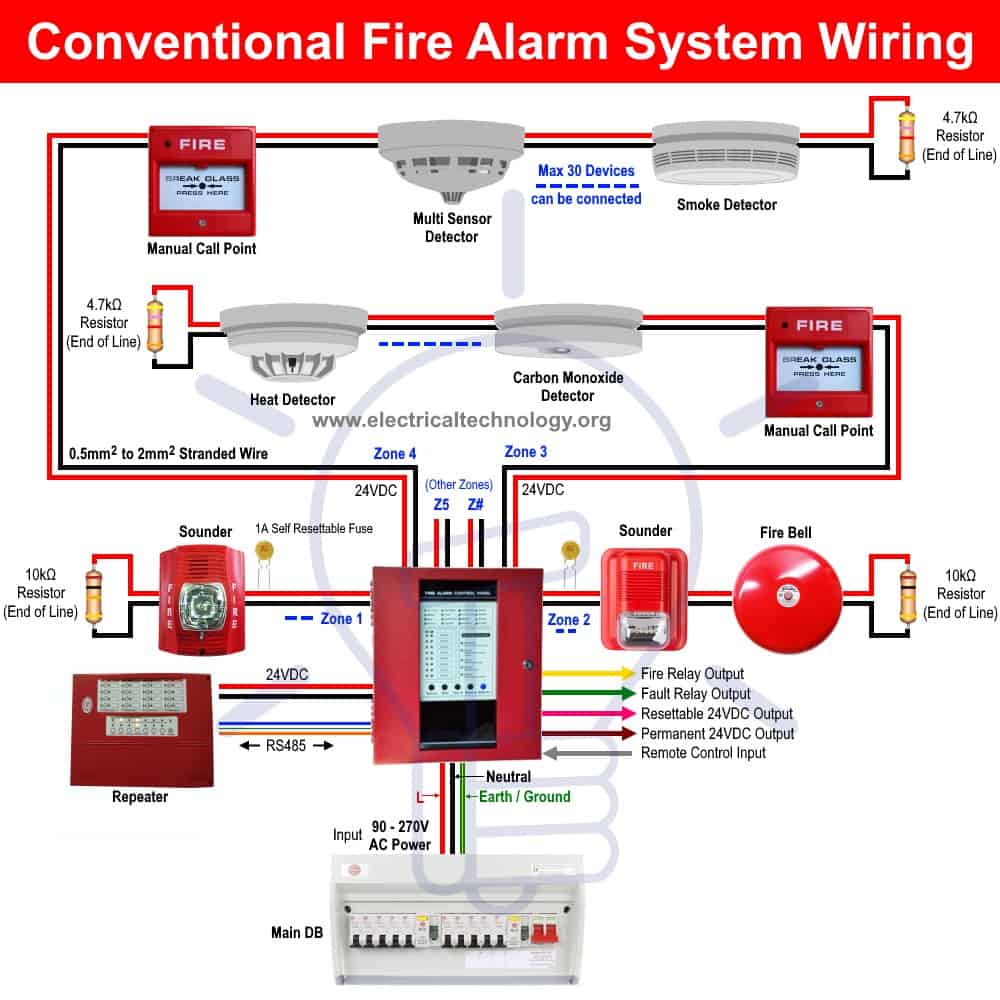
Conventional Fire Alarm System
In a conventional fire alarm system, all devices such as detectors, sounders and call points are connected to the control panel through separate wire or cable instead of shared one. In other words, the first end of the wire is connected to the detectors and second one to the control panel.
In a typical conventional fire alarm system, detectors, sounder and call points are installed and divided into different zones i.e. Zone 1 for basement, Zone 2 for ground floor, Zone 3 for first floor etc. This way, it is easy to identify the exact affecting area to the control room, building management and fire brigade. In other words, the more numbers of zones, the more accurate locating the trigger and fire location.
Keep in mind that the very accurate and exact location of fire can’t be found easily in a conventional fire alarm system as compared to the addressable fire alarm system. As the control panel won’t allow you to pinpoint the exact location of individual device or which device has been triggered but only shows the zone location by text, lamp indicator or both in case of emergency.
Wiring of Conventional Fire Alarm System
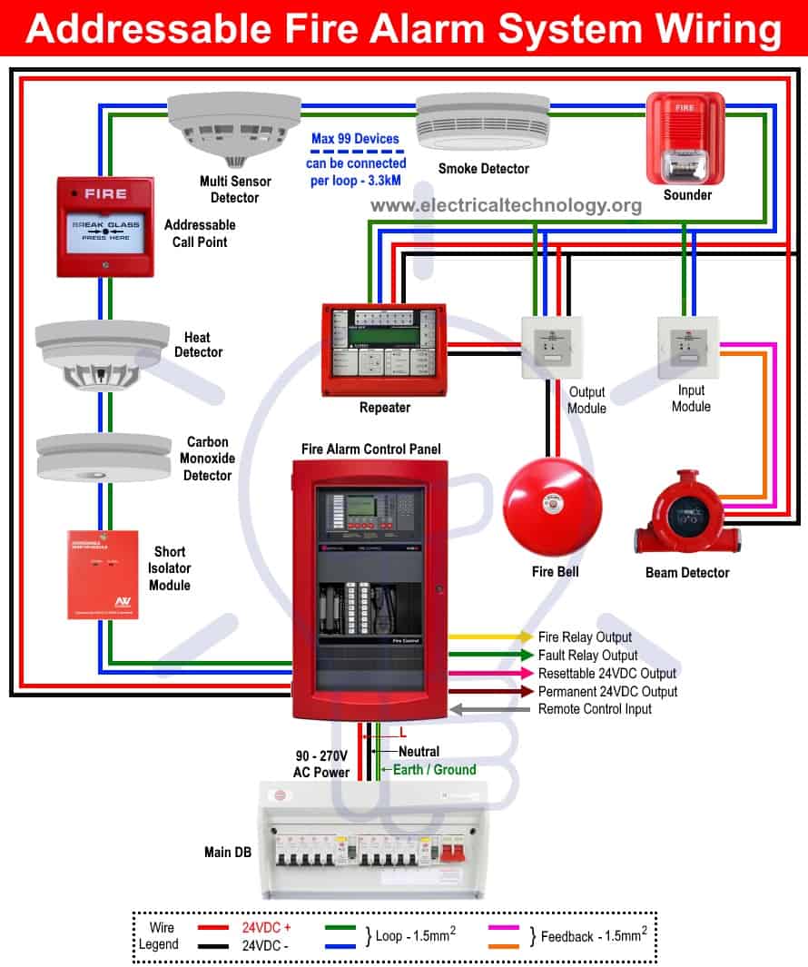
Addressable Fire Alarm System
In an addressable fire alarm system, all the devices such as detectors, call points and alarm bells are connected in a loop system to the fire addressable control panel and each device has an address (to tell about their location). This way, it is very easy to find the exact location of the device which has been triggered in the connected circuitry.
The basic idea behind the loop system is that in case of short circuit fault, only a small portion of the system affected while the rest will work properly with the help of isolation module connected in the loop. In a single loop, up to 99 devices may be connected and can be extended up to 3.3 km depends on the ability of fire control panel system.
The main purpose of addressable fire system is same as conventional fire system expect the wiring connection and DIP (Dual In-Line Package) switches for an address or a set of address showing the exact location of triggered component on main addressable fire control panel screen. Addressable is most accurate but costly as compared to conventional system while both are not smart as compared to intelligent fire system which show the exact reason behind the triggered device if it is a fault, pre-alarm or fire and extinguish them quickly.
Wiring of Addressable Fire Alarm System
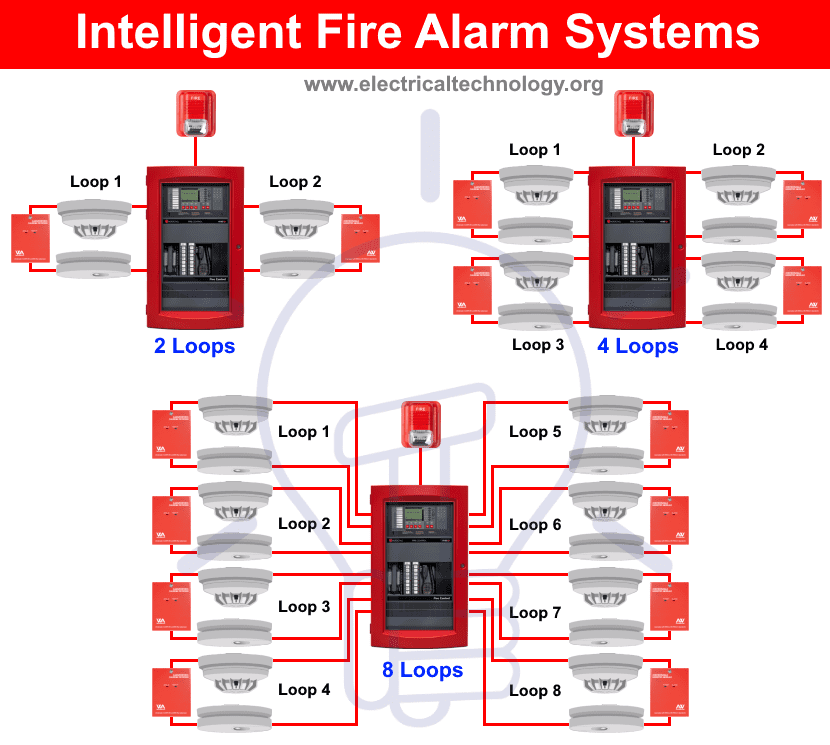
Intelligent Fire Alarm System
In an intelligent fire alarm system, each device has the ability to analyze the environment around it and communicate the central control panel to take further action(s) in case of fault, fire or the device needs cleaning or scheduled maintenance of the detectors.
As compared to the traditional fire alarm systems, they only provide single signal of info i.e. no matter if it is a fire, or other uncertainties such as fault, temperature, smoke particle or barometric pressure etc, it will trigger the alarm system which is considered as false positives. This misleading information can affect different phenomena such as reporting, omission etc.
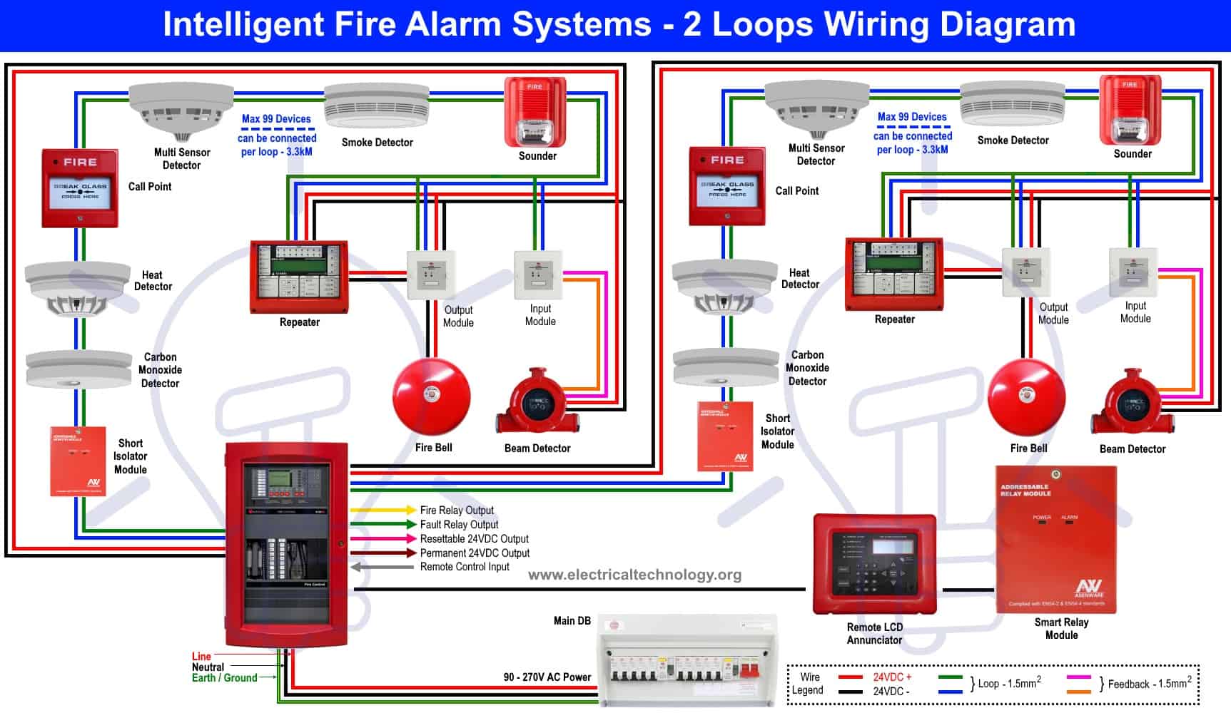
Similarly to the addressable fire control system, the devices are connected in loops in intelligent system which is available in two, four and eight loops system. A single loop can be extended up to 3.3km and up to 99 devices (such as sounders, detectors and call points) can be connected in a single loop. This way, a large area can be controlled and monitored from single control panel.
The main purpose of intelligent fire alarm system is to prevent the occurrence false alarms which need extra complexity due to high accurate sensors with incorporate computers system and algorithms. This way, it is more complex and expensive as compared to the traditional conventional and addressable fire detection systems.
Wiring of Intelligent Fire Alarm System
Click image to enlarge
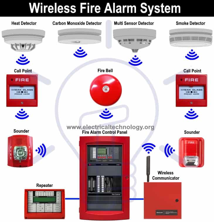
Wireless Fire Alarm System
In a wireless fire alarm system, all the detectors and related devices are interconnected remotely through radio communication to the fire control panel.
Please don’t kill me to tell you that there are wires and a cable in the wireless system as well, i.e. wireless system is not a wireless at all.
In the wireless fire alarm system, a radio signal is transmitted from the detector (such as heat detector) or call point to the central fire alarm system to activate the alarm circuit.
As wireless fire detection system is less costly due to labor costs and cable wiring with quick installation without shutting down the building areas for hours, but the hardware are very expensive even more in case of batteries replacement and maintenance.
Wiring if Wireless Fire Alarm System
Related Posts:
- How to Connect a Portable Generator to the Home Supply – 4 Methods
- How to Wire Auto & Manual Changeover & Transfer Switch (1 & 3 Phase)
- Single Phase Electrical Wiring Installation in Home – NEC & IEC
- Three Phase Electrical Wiring Installation in Home – NEC & EC
- Manual & Auto UPS / Inverter Wiring Diagram with Changeover Switch
-
 Difference Between Grounding, Grounded and Ungrounded Conductors
-
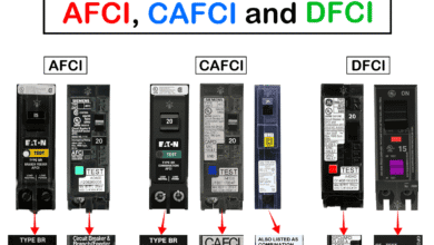 Difference Between AFCI, CAFCI, DFCI and GFCI?
-
 Can You Use a 2-Pole Breaker Instead of a 1-Pole Breaker
-
 What is the Life Expectancy of a Circuit Breaker?
-
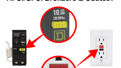 What Happens When You Press TEST and RESET on a GFCI
-
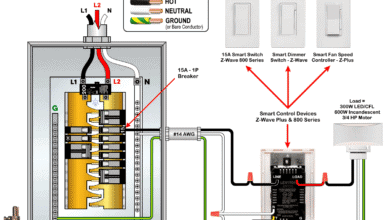 Wiring Z-Wave Smart Switch, Dimmer & Fan Speed Controller