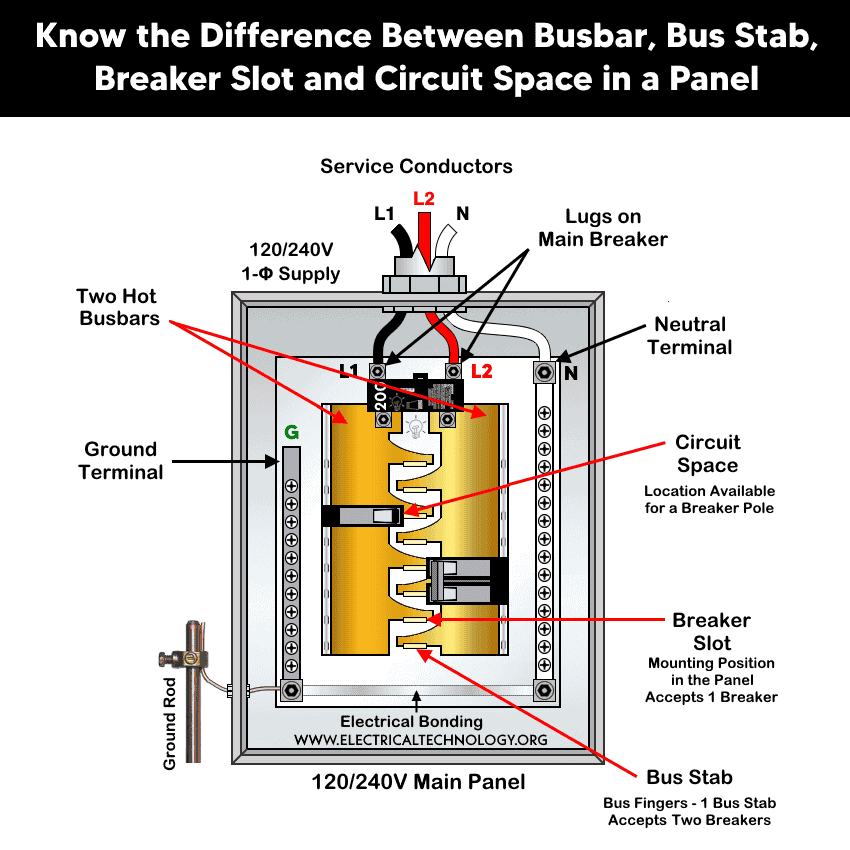
What are Busbars, Bus Stabs, Circuit Spaces, Breaker Slots, Neutral Terminals, and Ground Terminals in an Electrical Panel or Load Center?
Electric panels and load centers in residential and commercial applications have some different setting for breaker installation ad load circuit distribution. Most of them have busbars, neutral busbar, ground busbar, ground rod, main breaker, 1-pole and 2 pole breaker etc.
In this article, we will focus on snapping breakers for branch circuit conductors and explain related terms such as busbars, circuit space, breaker slots, and bus stabs.
Busbars
A busbar is the main conductive strip or bar inside the electrical panel that distributes power to all circuit breakers. In simple terms, the busbar is the main power rail inside the panel.
Hot Busbars
Hot busbars carries electrical power from the main breaker to the branch circuit breakers and acts as the central power distribution path inside the panel.
The above fig shows two vertical busbars used for Hot 1 (on the left) and Hot 2 (on the right) in a 120/240V single-phase residential electric panel.
Hot busbars usually made of copper or aluminum and designed to carry high current safely. Both busbars are connected to the main breaker via incoming power supply (power entrance conductors). They are typically arranged as two hot busbars in a 120/240V single-phase panel for 1-pole or 2-pole breaker connections. These busbars are rated according to the panel’s ampacity (e.g., 100 A, 200 A).
Good to Know: A 120V/240V single-phase panel has two hot busbars (Hot 1 and Hot 2), whereas a three-phase panel has three hot busbars (Hot 1, Hot 2, and Hot 3).
Neutral Busbar
A neutral busbar (also known as Neutral terminal) in an electrical panel is a metal conductor bar used to collect and distribute all neutral (grounded) conductors from branch circuits back to the supply neutral.
It is the common termination point for all neutral wires in a panel, providing a return path for current in AC circuits.
In a 120/240V single-phase system, hot wire carries current to the load and neutral wire returns current back to the source. In short, the neutral busbar connects all branch circuit neutral wires to the service neutral conductor.
The neutral busbar is made of aluminum or copper and usually located along the sides of the panel and connected to the neutral conductor from supply line.
Good to Know:
- At the main service panel, the neutral busbar is bonded to the grounding busbar.
- In subpanels, the neutral busbar must be isolated from the ground busbar and panel enclosure.
Ground Busbar
A ground busbar (also known as ground terminal) in an electrical panel is a metal bar used to terminate and connect all Equipment Grounding Conductors (EGCs) so that fault current can safely travel to ground and operate the overcurrent protection device.
The ground busbar is the common connection point for all grounding wires in a panel, linking them to the grounding system. These grounding conductors in the branch circuit conductors are typically bare copper, green with yellow strip or solid green insulated wires.
The primary purpose of the ground busbar is to provide a low-impedance path for fault current. For instance, If a hot conductor touches the metal case of an appliance, the grounding conductor carries the fault current through the ground busbar, allowing the circuit breaker to trip quickly.
It is used in equipment grounding and bonding i.e. all metal parts of electrical equipment are connected to the grounding system through the ground busbar. This includes all metallic parts i.e. electrical boxes, appliance frames, conduit systems, panel enclosures etc.
The ground busbar is made of aluminum or copper and usually mounted directly to the metal panel enclosure, installed on the side or bottom of the panel. It is connected directly to the ground rod ( via Ground Electrode Conductor “GEC”) and provided with multiple terminal holes for grounding wires.
Bus Stab
A bus stab in an electrical panel is the metal contact point on the busbar where a circuit breaker connects (clips on) to receive electrical power and distribute to the load through the branch circuit conductors. In simple words, The bus stab is the power contact point on the busbar.
Inside a panelboard or load center, there are busbars (usually two vertical hot busbars in a single-phase panel). These busbars distribute power from the main breaker to the branch circuit breakers.
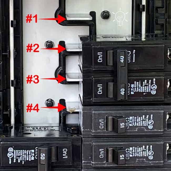
A bus stab (also known as bus fingers or bus connector) is the protruding tab the busbar designed for a breaker to snap onto and make electrical contact. Each hot busbar has two bus stabs, allowing two full-size breakers to connect one on the left side and one on the right side of the panel.
In the following figure, stab #2 and stab #4 belong to Hot 1 (left busbar), while stab #1 and stab #1 are part of Hot 2 (right busbar). This alternating pattern continues down the length of both busbars in the panel.
As shown in the fig, only one single-pole 120V breaker is connected to stab #4 and a 2-pole 240V breaker is connected to stab #2 and #3 (two opposite-phase bus stabs (Hot 1 and Hot 2) . There is no breaker attached to stab #1. It means, you may connect two additional standard or GFCI breakers to stab #1 or another breakers on the other side using the same stab i.e. 2, 3 or 4.
Good to Know:
- A 1-pole breaker can snap over a single slot i.e. single (either Hot 1 or Hot 2) busbar.
- A 2-pole breaker occupies two adjacent slots and connects to both busbars in a 120/240V panel.
Why it Matters
Despite the busbar and breaker ratings, the manufacturer specifies the “Maximum Sum of Breaker Rating per Stab”, which is usually indicated on the panel’s printed data label.
For example, the following figure shows that the maximum sum of breaker ratings per stab is 200A. This means the combined rating of breakers connected to the same stab must not exceed 200A.
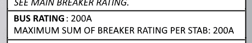
In this case, if a 125A breaker is installed on one side of the stab, the breaker on the opposite side should not be larger than 75A. In simple terms, the total rating of both circuit breakers connected to the same stab must not exceed 200A.
This limitation helps prevent excessive heat buildup at the bus stab connection, in accordance with the panel’s UL listing and manufacturer specifications.
Another case involves when connecting tandem breakers (also called duplex breakers) to the bus stabs.
In this situation, two breakers within a single tandem breaker unit connect to one bus stab. If tandem breakers are installed on both sides of the same stab, a total of four breakers (in two tandem units) may be connected to that single stab.
Even in this configuration, the combined rating of all breakers connected to the same stab must not exceed the manufacturer-specified maximum sum of breaker ratings per stab.
Breaker Slot
A breaker slot is the physical mounting position in the panel where a circuit breaker is installed.
A slot aligns with a bus stab on the busbar. One breaker slot typically accepts one full-size breaker. In some panels, the slot can accept two tandem breakers.
for example, If a panel has 20 slots, it means there are 20 physical positions for breakers.
Good to Know:
- A 1-pole tandem breaker can snap over a single slot i.e. both the circuit are connected to a single (either Hot 1 or Hot 2) busbar.
- A 2-pole breaker tandem occupies two adjacent slots and both 240V circuits connects to both busbars in a 120/240V panel.
Circuit Space
A circuit space refers to the physical space in the panel intended to hold a circuit breaker pole.
Many manufacturers use circuit space and breaker slot as the same concept, but technically:
- Circuit Space = Location available for a breaker pole
- Breaker Slot = Mounting position in the panel
For instance, a panel labeled 20 spaces / 40 circuits means 20 circuit spaces for 20 physical breakers. If compatible, you can use maximum 40 individual circuits using 20 duplex breakers as each space can hold two circuits using tandem breakers.
Good to know:
A circuit is the electrical path that supplies power to loads such as lights, receptacles, or appliances.
It includes a circuit breaker, branch circuit conductors and load devices such as outlet, receptacle, lighting point, fan etc. For instance, A 15A breaker feeding 15A receptacles in a room is one branch circuit.
Precautions:
- Always disconnect the power supply by switching OFF the circuit breaker at the main service panel before performing any electrical work.
- Electrical equipment must be installed according to manufacturer instructions as required by the NFPA and NEC 110.3(B)).
- Never touch the terminal screws above the main breaker. These terminals are always energized and remain live even when the main breaker is switched OFF.
- If you are unsure about any part of the installation, consult a licensed electrician and ensure compliance with applicable local electrical codes.
Disclaimer: Electrical work is dangerous. The author assumes no responsibility for any loss, injury, or damage resulting from the use or misuse of this information, including improper circuit installation.
Resources:
Related Posts:
- National Electrical Code (NEC) Requirements for Panelboards
- What is Double Tapped Breaker and Double Lug in Main Panel
- What Happens if the Neutral is Lost in the Main or Subpanel?
- Why Must Neutral and Ground Wires Be Bonded in the Main Panel?
- Why are Neutral and Ground Wires Separated in a Subpanel?
- Should GFCI Protection Be in the Main Panel or Receptacle?
- Difference Between BR and CH Breakers and Load Centers
- Difference Between Homeline and QO Breakers and Panels
- Difference Between 1-Pole and 2-Pole Breakers – NEC & IEC
- Can the Neutral Wire Cause Electric Shock? Different Cases
- Will I Get an Electric Shock If I Touch the Ground Wire?
- Will a Man Get an Electric Shock If He Hangs on a Live Wire?
- What Happens When You Touch an Electrical Busbar?
- Can We Use AC Circuit Breaker for DC Circuit & Vice Versa?
- Can I Use a 240V Breaker on a 120V Circuit and Vice Versa?
- Can You Use 15A Breaker on 20A Circuit and Vice Versa?
- What is the White Powder on the Circuit Breaker Terminals?
- Why Doesn’t a Standard Breaker Protract Against Ground Faults?
Sizing & Rating
- How to Size a Load Center, Panelboards and Distribution Board?
- How to Determine the Right Size Capacity of a Subpanel?
- How to Size a Circuit Breaker? Breaker Size Calculator
- How to Determine the Number of Circuit Breakers in a Panel Board?
- How to Find the Right Wire Size for 100A Service 120V/240V Panel?
- What is the Correct Wire Size for 100A Breaker and Load?
- How to Find the Number of Lights on a Single Circuit Breaker?
- How to Size a Breaker and Wires in AWG with EGC for Load?
- How to Size a Branch Circuit Conductors with Protection?
- How to Size Feeder Conductors with Overcurrent Protection
- How to Size Service-Entrance Conductors and Feeder Cables?
- How to Size Equipment Grounding Conductor (EGC)?
- How to Size Grounding Electrode Conductor (GEC)?
- How to Find the Proper Size of Wire & Cable In Metric & Imperial Systems
Wiring Tutorials
- How to Wire 120V & 240V Main Panel? Breaker Box Installation
- How to Wire a Subpanel? Main Lug Installation for 120V/240V
- How to Wire 120V & 208V – 1 & 3-Phase Main Panel? 3-Φ Load Center Wiring
- How to Wire a GFCI Circuit Breaker? 1, 2, 3 4 Poles GFCIs Wiring
- How to wire a GFCI Outlet? GFCI Wiring Circuit Diagrams
- How to Wire an AFCI Combo Switch – AFCI Switch Wiring Diagrams
- How to Wire a Single-Pole Circuit Breaker in a 120/240V Panel
- How to Wire a Two-Pole Circuit Breaker in a 120/240V Panel
-
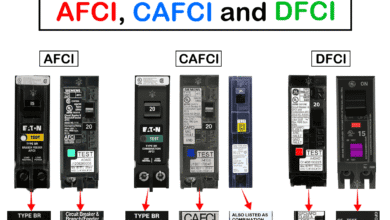 Difference Between AFCI, CAFCI, DFCI and GFCI?
-
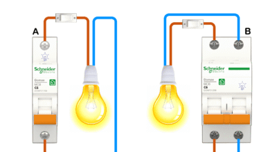 Can You Use a 2-Pole Breaker Instead of a 1-Pole Breaker
-
 What is the Life Expectancy of a Circuit Breaker?
-
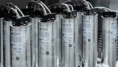 Why is a Capacitor Bank Rated in kVAR, Not in Farad?
-
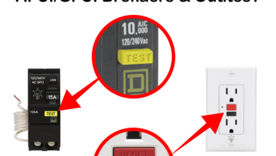 What Happens When You Press TEST and RESET on a GFCI
-
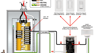 Wiring Z-Wave Smart Switch, Dimmer & Fan Speed Controller