Single Phase Electrical Wiring Installation in Home – NEC & IEC
How to Wire a Single Phase Distribution Board & Consumer Unit in Home
Single Phase 120V/230V Distribution and Panel Board Wiring in Home
Single Phase wiring installation is the most common wiring in residential buildings. In Single Phase supply (230V in UK, EU and 120V & 240V in the US & Canada), there are two (one is Line (aka Phase, Hot or Live) and the other one is Neutral) incoming cables from the utility poles to the kWh energy meter and then directly connected to the main distribution board (Consumer unit).
In this step by step tutorial, we will show how to wire a single Phase Consumer Unit Installation in home from Utility Pole to a Single-Phase Energy Meter & Single-Phase Distribution board and then How to connect Single Phase Loads in single Phase Wiring Distribution System in home electric supply system.
Before go in details, you will have to know what is a Single Phase and Three Phase Supply, their applications as well as the role of RCD, MCB, MCCB, CB, DB, MDB, Final and Sub Circuits, Fuses, Switches etc. which is already discussed in our previous electrical wiring installation tutorials.
Related Wiring Tutorials:
- Three Phase Electrical Wiring Installation in Home – NEC & IEC
- Single-Phase Electrical Wiring installation in a Multi-Story Building
- 3-Phase & 1-Phase Electrical Distribution Wiring Installation in Multistory Building
Single Phase & Three Phase Voltage Levels in the US – NEC
The following different levels of voltages are available for domestics (as residential) and commercial (as industrial) application in the US, Canada (following NEC and CNC) and UK, EU and other countries which follows the IEC e.g. India, Pakistan, UAE, KSA, Philippine, South Africa, Nigeria, Indonesia etc. The following fig at the end of this section will help you easily understand the difference between single phase and three phase voltage levels in the NEC and IEC.
In the USA, for single phase 120V and split phase or 240V, the secondary winging of the distribution transformer mounted on the utility pole is center-tapped i.e. two hot wires (Hot 1 and Hot2) and the center wire as Neutral. This way, the voltage level between Hot and Neutral is 120V single phase and voltage between two hots (Hot 1 & Hot 2) is 240V single phase.
Single Phase Voltage Levels in the USA
- Line or Hot to Neutral = 120V,
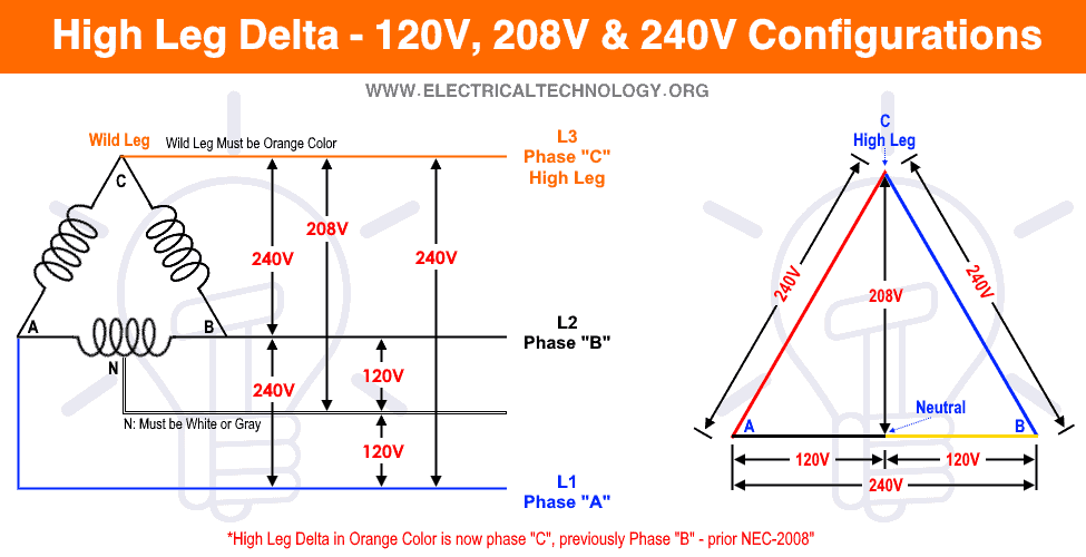
- Hot to Neutral = 208V, (High Leg Delta)
- 2 Hot = 240V (split phase),
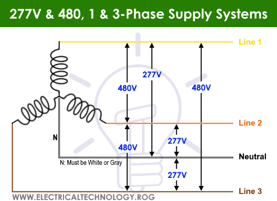
- Hot to Neutral = 277V
- Hot to Neutral = 480V
Three Phase Voltage Levels in the USA
- Three Hots = 208V
- Three Hots = 240V
- Three Hots = 480V
i.e.
- L1 to N = 120V, 208V, 277V or 480V – (1-Φ)
- L2 to N = 120V, 208V, 277V or 480V – (1-Φ)
- L3 to N = 120V, 208V, 277V or 480V – (1-Φ)
And
- L1 to L2 = 208V, 240V or 480V – (3-Φ)
- L2 to L3 = 208V, 240V or 480V – (3-Φ)
- L3 to L1 = 208V, 240V or 480V – (3-Φ)
Related Wiring Tutorials:
Single Phase & Three Phase Voltage Levels in the UK, EU – IEC
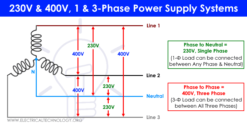
In a Three Phase Wiring Distribution System (Star Connection i.e. 3 Phase, 4 Wire System); The power and distribution transformers may be wired in Star (Y) or Delta configuration). For example, the basic configuration for single phase and three phase system in the UK is 230V/400V where the primary of the distribution transformer mounted on the utility pole is connected in Delta Connection while the secondary is connected in Star or Y Connection.
This way, the Voltage between any phase and neutral is 230V single phase, while the voltage level between three lines are 400V three phase.
Single Phase Voltage Levels in the UK & EU
- Phase to Neutral = 230V
Three Phase Voltage in the UK & EU
- Phase to Phase = 440V
- Any Phase to Neutral = 230V Single Phase
- Between Three Phase = 440V Three Phase
I.e.
- L1 to N = 230 V – (1-Φ)
- L2 to N = 230 V – (1-Φ)
- L3 to N = 230 V – (1-Φ)
And
- L1 to L2 = 400 V – (3-Φ)
- L2 to L3 = 400 V – (3-Φ)
- L3 to L1 = 400 V – (3-Φ)
120V, 208V, 240V, 277V & 480V, Single Phase and Three Phase Supply Voltage Systems – NEC – US
120V, 208V & 240V High Leg Delta Configurations
230V & 400V Single Phase & Three Phase Power Supply Systems – IEC – UK & EU
Related Wiring Tutorials:
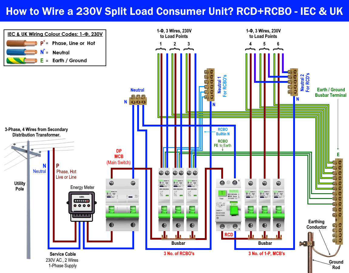
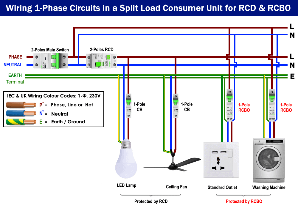
- How to Wire 1-Phase Split Load Consumer Unit? – RCD+RCBO
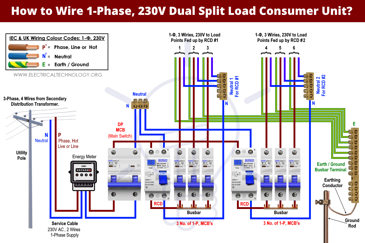
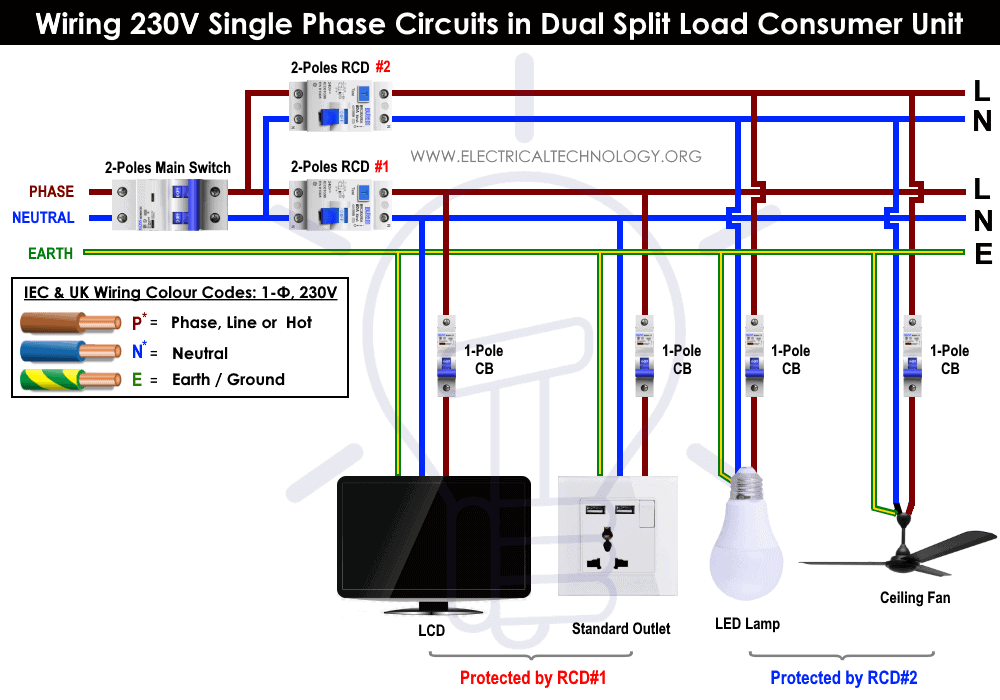
- How to Wire 230V Dual Split Load Consumer Unit? – RCD+MCB
Requirements for Single Phase Wring Installation in Home
| Required Materials | Number |
| Single Phase Energy Meter | 1 |
| Two Pole MCCB: 63A to 100 A | 1 |
| Double Pole: 63A, 30mA Trip Current (RCD/GFCI) | 3 |
| Double Pole MCBs: 63A | 3 |
| Single Pole MCBs: 20A | 6 |
| Single Pole MCBs:16A (15A in US) | 3 |
| Single Pole MCBs: 10A (15A in US) | 6 |
| Distribution Board Cases | 3 |
| Copper strips for MCB common connection | 3 (Cu Busbar segment) |
| Copper strip Busbar for Earth & Ground Link | 1 (Cu Busbar segment) |
Related Posts:
How to Wire Single Phase Main Distribution Board?
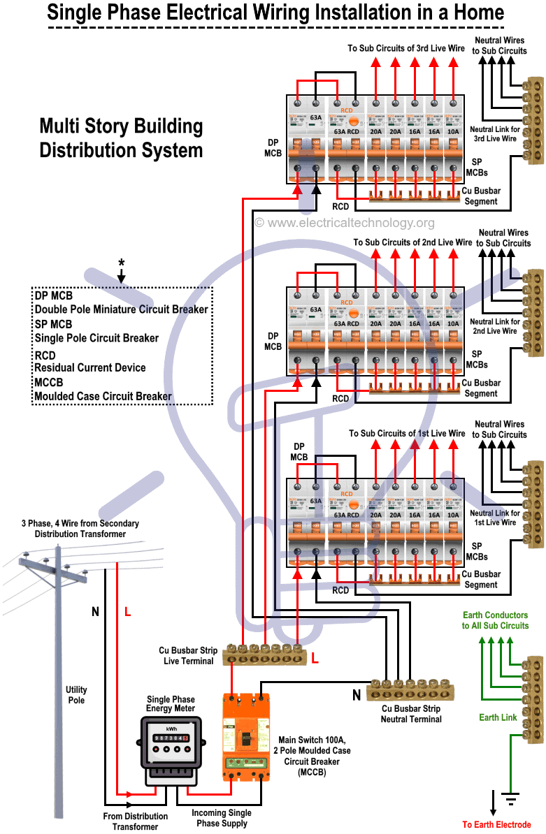
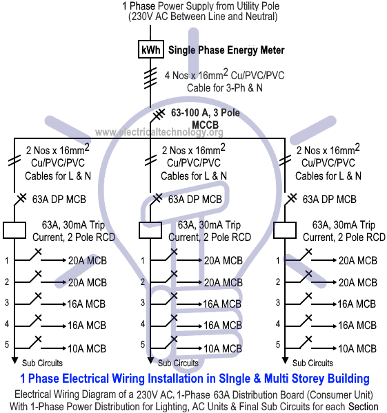
To Wire and install a single phase consumer unit for electric supply distribution in multi sections of a house, follow the steps given below:
- Connect the Incoming Live and Neutral (L and N) wires from the electric utility pole to the Single Phase Energy meter. If you are not sure how to do it, here is a step by step tutorial on How To Wire a Single Phase Energy meter).
- Connect the Incoming Live and Neutral (L and N) Wires to the 2 Pole Molded Case Circuit Breaker “MCCB” as shown in fig 1. It will be used as a main switch for all sections in the home.
- Connect the MCCB to the Double Pole MCB’s, RCD, Single Pole MCBs respectively for each section and the outgoings wires and cable to the sub circuits and final sub circuits. Do the same steps for each section (3 Switch boards in our case). Keep in mind that proper connection should be done for Neutral and Live wires in the whole system as shown in fig 1. If confused, wiring color codes for IEC and NEC are given below in the info section for both single phase and three phase wiring.
- Now, connect the electrical devices and appliances with the Earth link terminal which leads to earth electrode in the earthing and grounding system as shown in fig 1.
- Do the same steps for all three distribution boards and consumer units for other sections i.e. basement, garage etc.
Related Posts:
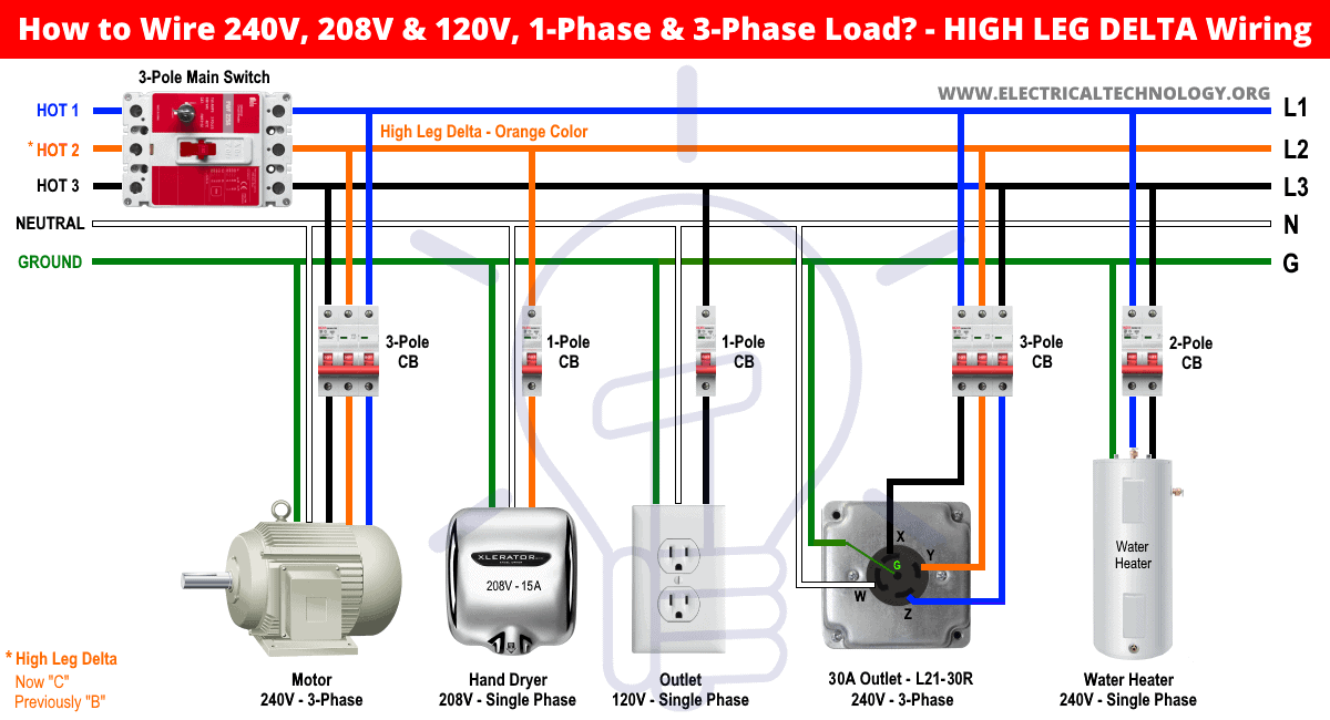
- How to Wire 240V, 208V & 120V, 1 & 3-Phase, High Leg Delta Main Panel?
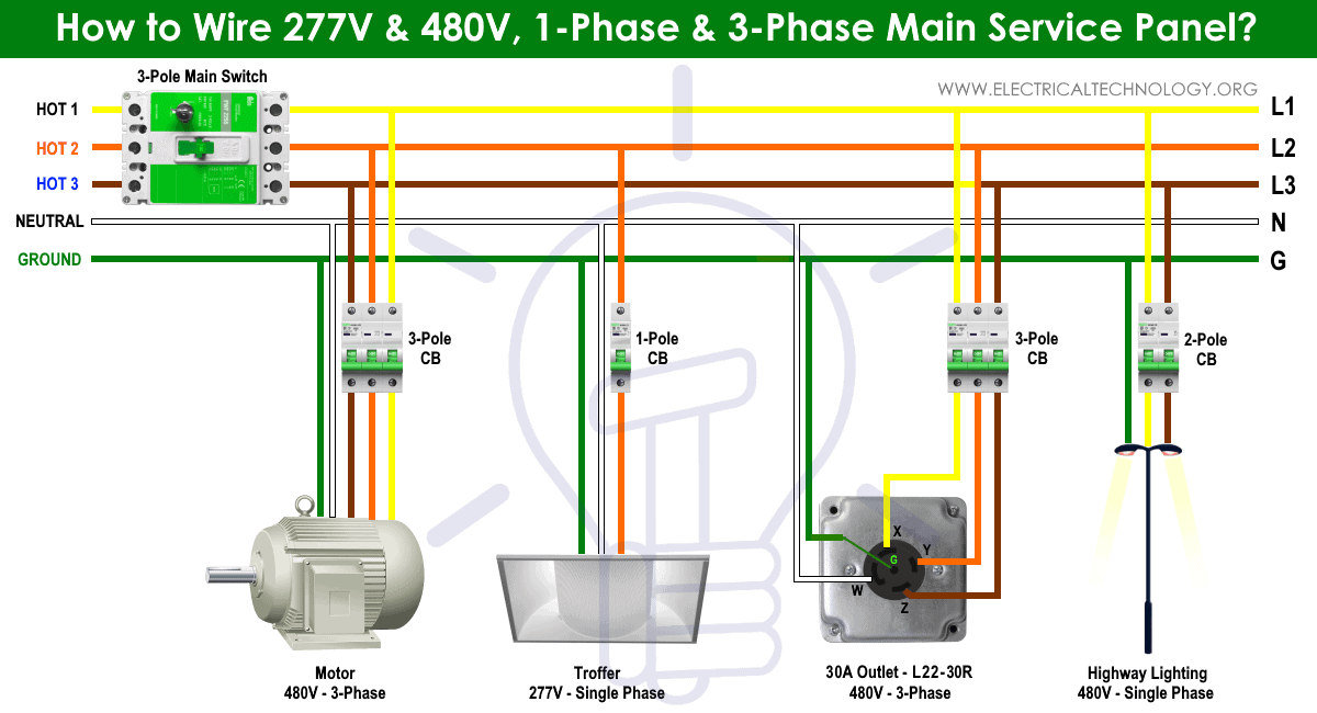
- How to Wire 277V & 480V, 1-Phase & 3-Phase, Commercial Main Service Panel?
Click image to enlarge
If you have to install a single phase mains distribution system in different sections around the home (large area), follow the following important things before doing so.
- As we showed in the fig 1, use separate main breaker and boards for each section (3 different sections in our case). This way, electric supply would not be interpreted on other sections if one of the CB or MCB trips due to faults (Short Circuit etc.). The whole system will go off at once if we connect each section load (Fans, Light etc.) directly to the main distribution board.
- If we use a single circuit instead of three circuits for each section, high current will flow through the whole circuit if load of a single section increases which cause overheating the wires and cables. So there may be a risk of electric fire and hazard as well due to overheated cables In the building. Moreover, due to more current flowing in the cable, voltage drop may be increased and there the appliances and devices may not get the proper and rated voltage, so they might not work properly.
- Use the proper cable size and rated main breaker. In other words, the main breaker should be capable of handling loads of all sections around the home. The same should be done for DP and SP breakers in sub distribution boards which should handle the load (Lighting points , washing machine, fans etc.) of the desired section for sub and final sub circuits.
Related Posts:
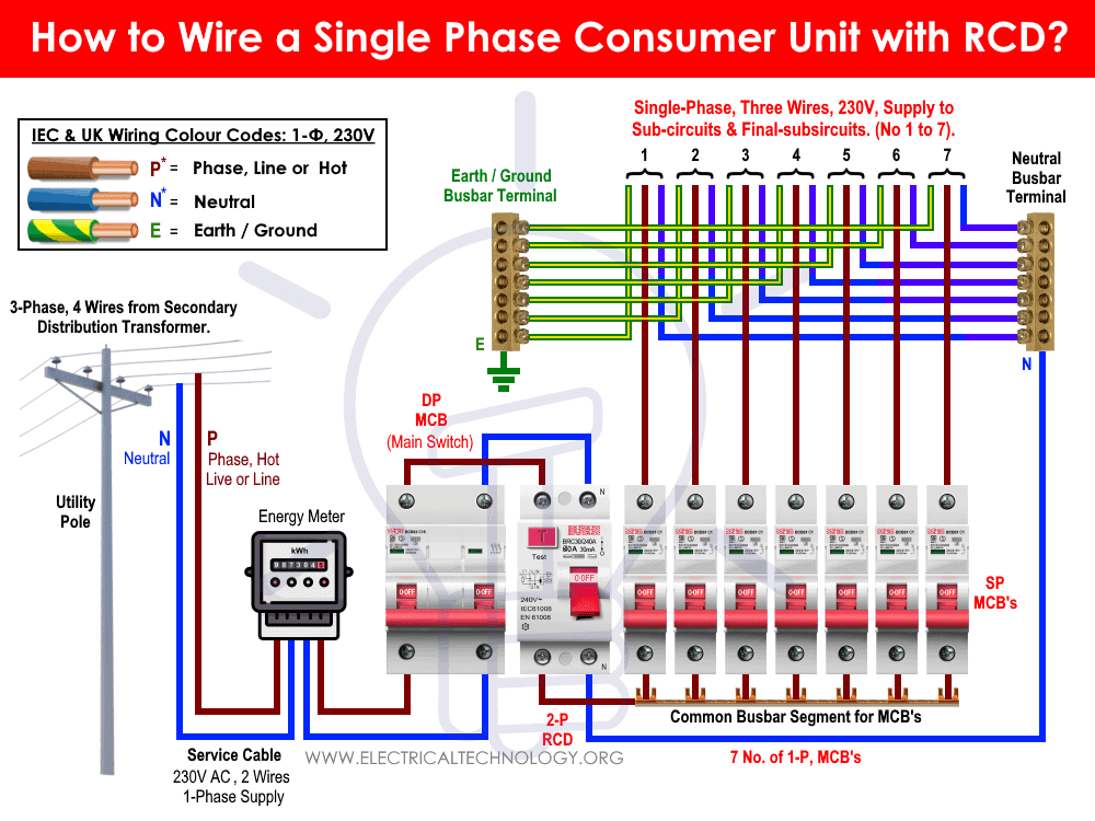
- How to Wire Single-Phase, 230V Consumer Unit with RCD? IEC, UK & EU
- How to Wire 1-Phase & 3-Phase Split Load Distribution Board?
- How to Wire Automatic UPS / Inverter to the Home Supply System?
Single Phase Electrical Wiring Installation Diagrams According to NEC Color Codes
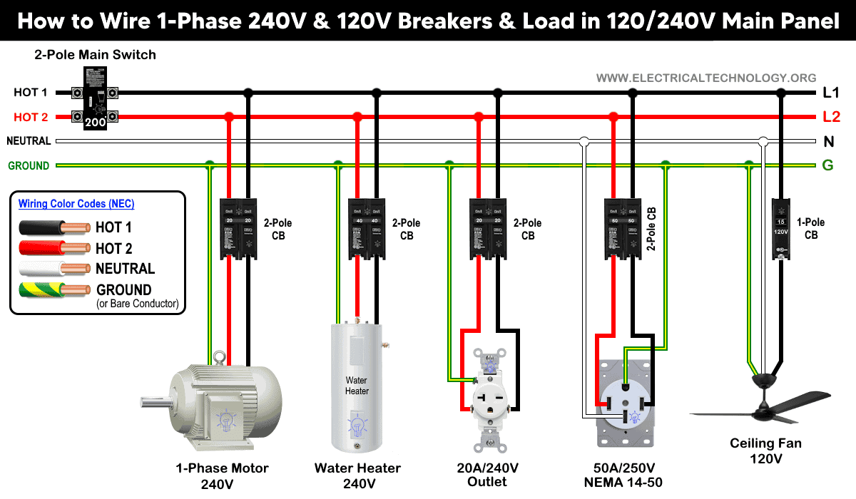
Single Phase 120V & 240V Distribution and Panel Wiring in home.
Click image to enlarge

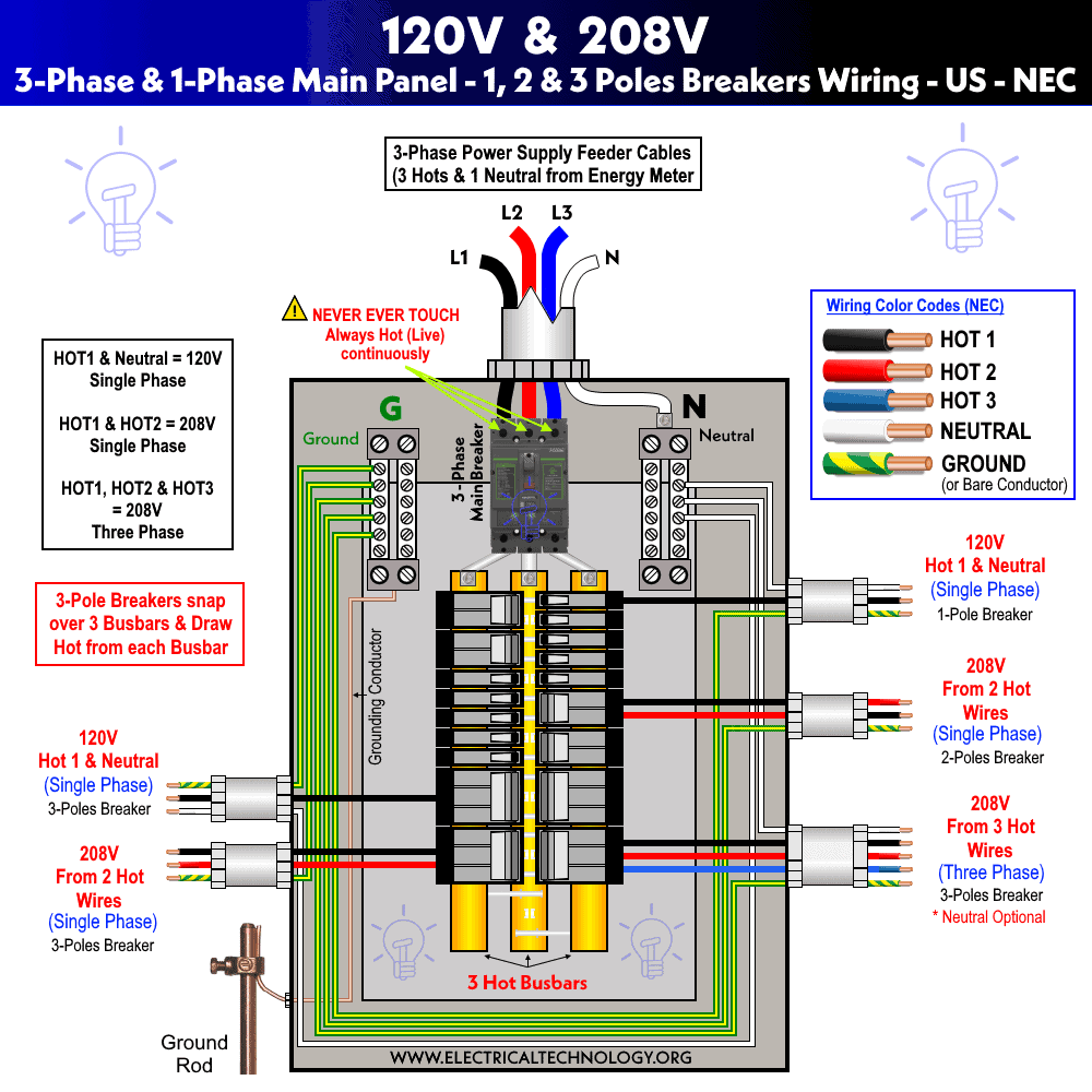
Single Phase 120V & 208V Distribution and Panel Wiring in home.
Click image to enlarge
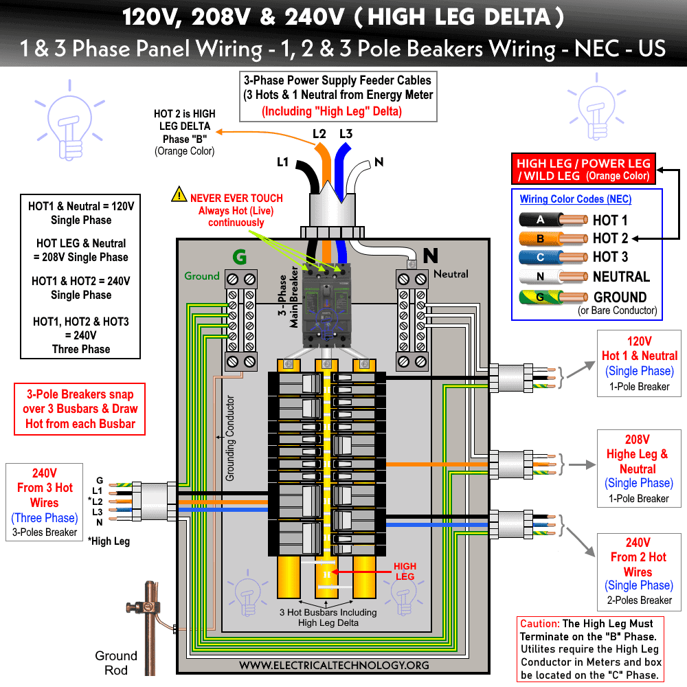
Single Phase 120V & 208V & 240V (High Leg Delta) Distribution and Panel Wiring in home.
Click image to enlarge
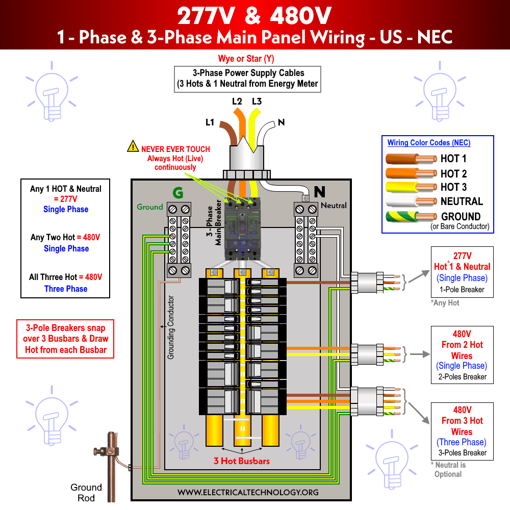
Single Phase 277V & 480V Distribution and Panel Wiring in home.
Click image to enlarge
Related Posts:
Single Phase Electrical Wiring Installation Diagrams According to IEC Color Codes
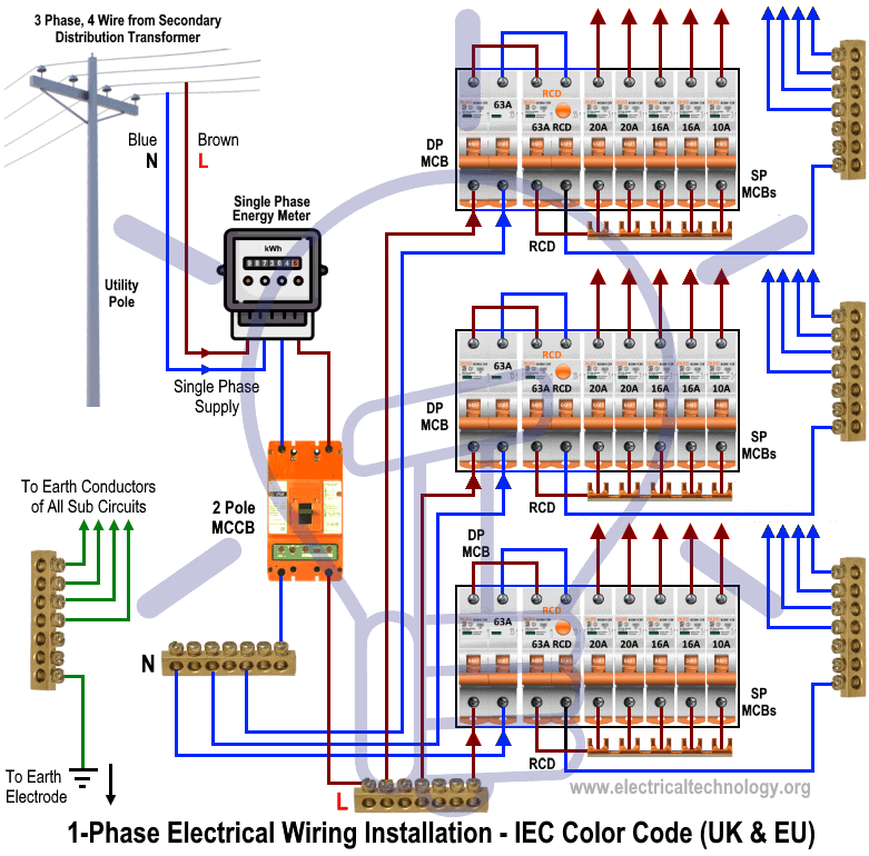
Single Phase 230V Distribution and Consumer Unit Wiring in Multi-sections of home.
Click image to enlarge
Single Phase, 230V Consumer Unit & Distribution Board Wiring with RCD
Click image to enlarge
Single Phase, 230V Split Load Consumer Unit & Distribution Board Wiring
Click image to enlarge
Single Phase, 230V Dual Split Load Consumer Unit & Distribution Board Wiring
Click image to enlarge
Related Posts:
- Staircase Wiring Circuit Diagram – How to Control a Lamp from 2 Places?
- Corridor Wiring Circuit Diagram – Hallway Wiring using 2-Way Switches
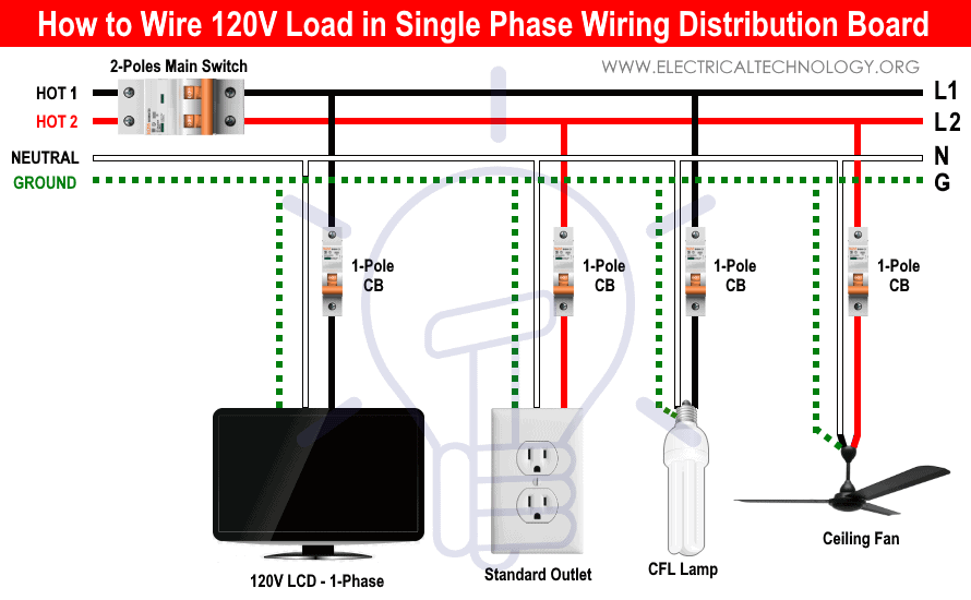
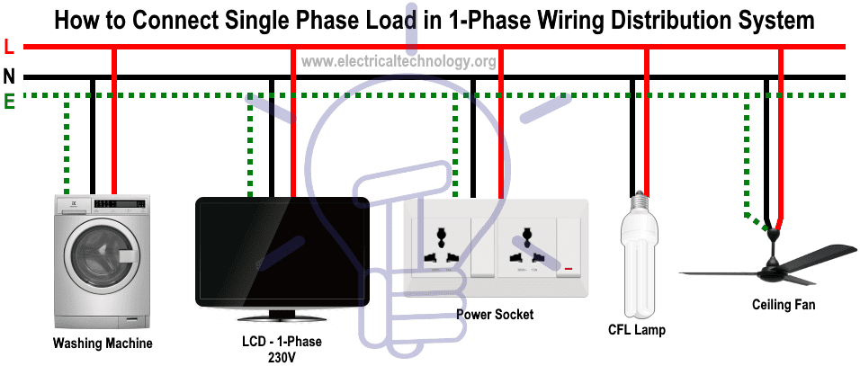
How to Connect Single Phase 120V Loads in a 1-Phase Wiring Distribution System? – NEC, US & Canada
There is no much difference in IEC and NEC wiring for single phase MCB’s and associated wiring i.e. a single phase expect for 240V. In other words, 120V single phase load can be connected directly to the single pole MCB via three wires e.g. Black as Hot, White as Neutral and green with yellow stripe or bare conductor as protective ground.
In 240V single phase wiring, the load can be connected to the double pole MCB via three or four wires (as Neutral is always needed in that case and depends on the system design) i.e. Black as Hot 1, Red as Hot 2, White as Neutral (optional) and green/yellow stripe or bare conductor for ground wire.
Below are some typical single phase wiring diagrams used for power distribution in the home (United States of America and Canada).
Wiring Installation of Single Phase 120V Circuits & Breakers in Main Service Panel
Wiring Installation of Single Phase 120V & 240V Circuits & Breakers in Main Service Panel
Wiring Installation of Single Phase 120V & 208V Circuits & Breakers in Main Service Panel

Wiring Installation of Single Phase 120V, 208V & 240V (High Leg Delta) Circuits & Breakers in Main Service Panel
Wiring Installation of Single Phase 277V & 480V Circuits & Breakers in Main Service Panel
Related Posts:
How to Connect Single Phase, 230V Loads in a 1-Phase Wiring Distribution System? – IEC & UK
For Single Phase Loads (230V or 120V) Washing Machines, TV, Power socket, Lighting Points, Fans etc., can be directly connected to the Phase and Neutral wire through proper wiring and controlling as shown below. Note that Earth or ground wire must be connected to each of the electrical appliances and equipment connected to both single phase and three phase supply systems to avoid electric shock and hazard.
Wiring single phase 230V load and MCB in the Distribution board and consumer unit with RCD.

Wiring single phase 230V Split Load load and MCB in the Distribution board and consumer.
Wiring single phase 230V Dual Split Load load and MCB in the Distribution board and consumer.
Related Posts:
Wiring Diagram of single Phase Distribution Board In Home
Below is given layout wiring diagram of single phase consumer unit installation in a residential area.
Related Posts:
Electrical Wiring Color Codes – NEC and IEC
NEC – USA: Single Phase 120V AC: Single Phase 240V AC: Three Phase 208V & 240V AC (High Leg Delta): Three Phase 277V & 480V AC: IEC & UK: Single Phase 230V AC: Three Phase 400V: For reference, here is the OLD UK Wiring Color Codes (Prior 2004) which still applicable in other countries i.e. India, Pakistan, UAE, KSA and other Arab Countries. 400V Three Phase 230V Single Phase
Related Posts:
General Precautions & Instructions
- Electricity is our friend as well as enemy at the same time, if you give it a chance to kill you, Remember, they will never miss it. Please read all caution and instruction while doing this tutorial in practical.
- Disconnect the power supply (and make sure it is really swathed OFF) before servicing, repairing or installing electrical equipment. To do so, switch off the main switch in the main consumer unit or distribution board.
- Never stand or touch wet and metal parts while repairing or installation.
- Read carefully all the cautions and instructions and follow them strictly while doing this tutorial or any other work in practical related to electrical works.
- Always, use the right size cable and wire, proper size outlets and switch and suitable size of circuit breakers. You may also use the Wire and Cable size calculator to find the right gauge size.
- Never ever try to play with electricity (as it is dangerous and can be fatal) without proper guidance and care. Do the installation and repairing work in presence of experienced persons having vast knowledge and good practice who knows how to deal with electricity.
- Doing your own electrical work is dangerous as well as illegal in some cases. Contact the licensed electrician or the electric power supply provider before practicing any change/modification in electrical wiring connections.
- The distribution board should not be installed 2.2 meter (84 Inches = 7ft) while the disconnect switch should be installed 1.82 meter (72 inches = 6 ft) above the floor, must be protected from the corrosion and away from watery areas. All the wires should be covered in the panel board (i.e. it should not hang outside the panel). Finally, there must be a safety sign near the distribution board.
- The author will not be liable for any losses, injuries, or damages from the display or use of this information or if you try any circuit in wrong format. So please! Be careful because it’s all about electricity and electricity is too dangerous.
You may also check the related Electrical Wiring Installation Tutorials.
- Staircase Wiring Circuit Diagram – How to Control a Lamp from 2 Places?
- Corridor Wiring Circuit Diagram – Hallway Wiring using 2-Way Switches
- Tunnel Wiring Circuit Diagram for Light Control using Switches
- Hospital Wiring Circuit for Light Control using Switches
- Hotel Wiring Circuit – Bell Indicator Circuit for Hotelling
- Hostel Wiring Circuit Diagram and Working
- Godown Wiring Diagram – Tunnel Wiring Circuit and Working
- How to Wire 120V Water Heater Thermostat – Non-Simultaneous?
- How to Wire a Pilot Light Switch? Wiring of 2 & 3 Way Neon Light Switches
- How to Connect a Portable Generator to the Home Supply – 4 Methods
- Even More Electrical Wiring Installation & Tutorials


nice theory.but i need to know measures after installation
Hello,
What is the best practice to wire a 3 bedroom apartment with two toilet, a kitchen, a seating room and 4 outdoor security lamps. However i will like to know the how many circuit braker and ratings that will be needed for, lamps, sockets, 2 water heater, etc
Thanks in advance and looking forward to hearing from you.
Regards
Ebai Richard
Whatsapp: +237679340379
Have need of a circuit to control 3 d.c. air horns with 3 separate n o switches with 1 common power supply. Any switch can turn on all horns at same time. Also could use a single timer to control horns but also must be able to be as an emergency alarm system. And have a command switch from the front office to override all in paralel. Any other questions- my phone is 951-858-3242 i am maintenance leadman at a manufacturing plant.
How do we calculate the number of single pole MCBs and double pole MCBs to be used for a wiring installation?
Dear Sir,
You are giving very good knowledge useful for electrical family.I request you to please send electrical technology subject to my mail also.
I want a book tutorial for single and three phase home wiring
Toss information will our learners very important
Hello this theory is very important and very nice
Hi, how do I connect the wires from the lower changeover slots to the main db?
I’m electrician. Thank you for the wiring tutorials. Waiting for me.