Manual & Auto UPS / Inverter Wiring Diagram with Changeover Switch
How to do Manual & Auto UPS / Inverter Wiring with Changeover / ATS Switch
In our previous UPS / Inverter wiring diagrams & connections for home, we show that how to wire and connect an automatic UPS and batteries to the home distribution board for continues power supply. In today UPS / Inverter installation tutorial, we will show how to connect and install the battery backup power through automatic and manual UPS with the help of manual and automatic changeover switch and ATS (Automatic Transfer Switch) to the main switchboard panel box.
- Related Wiring Tutorial: How to Connect Automatic UPS / Inverter to the Home Supply System?
In the following article, There are different UPS and Inverter wiring and installation methods where some of the home appliances will depends on battery power in case of power failure while in other methods, all the home wiring connected directly to the UPS system for continues power supply in case of emergency breakdown.
In the following step by step tutorial, We will be showing:
- UPS / Inverter connection with Manual Changeover Switch (Partial Load)
- UPS / Inverter connection with Manual Changeover Switch (All Load)
- UPS / Inverter connection with Automatic Changeover Switch
- UPS / Inverter connection without ATS & Changeover Switch
Note: Use 6 AWG (7/064″ or 16mm2) cable and wire size to connect the UPS to the main panel board.
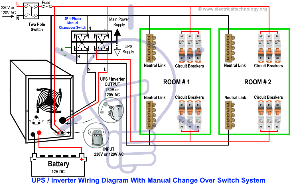
How to Wire UPS with Manual Changeover Switch? (Partial Load)
In this methods of wiring, the battery and UPS has been connected directly to the main supply where the output of the UPS has been connected to the partial load (specific appliances where we need continues power supply in case of power failure) with the help of two pole single phase manual changeover switch. In the following diagram, some of the breaker for specific load in the rooms has been connected to the output of the UPS where we need continues power supply.
When the utility power is not available, the battery will supply the power to the connected appliances through UPS while the rest load would remain inactive due to absence of main power as they are connected to the utility power only.
When main power restores from the power house, all the connected appliances would operate as normal as all the appliances are connected to the main power. Also, the Inverter will charge the battery as well as it has been connected to main power.
Keep in mind that it is the manual operation and you would have to change the changeover switch position manually when shifting the power from “Main” to “UPS” and vice versa.
Click image to enlarge
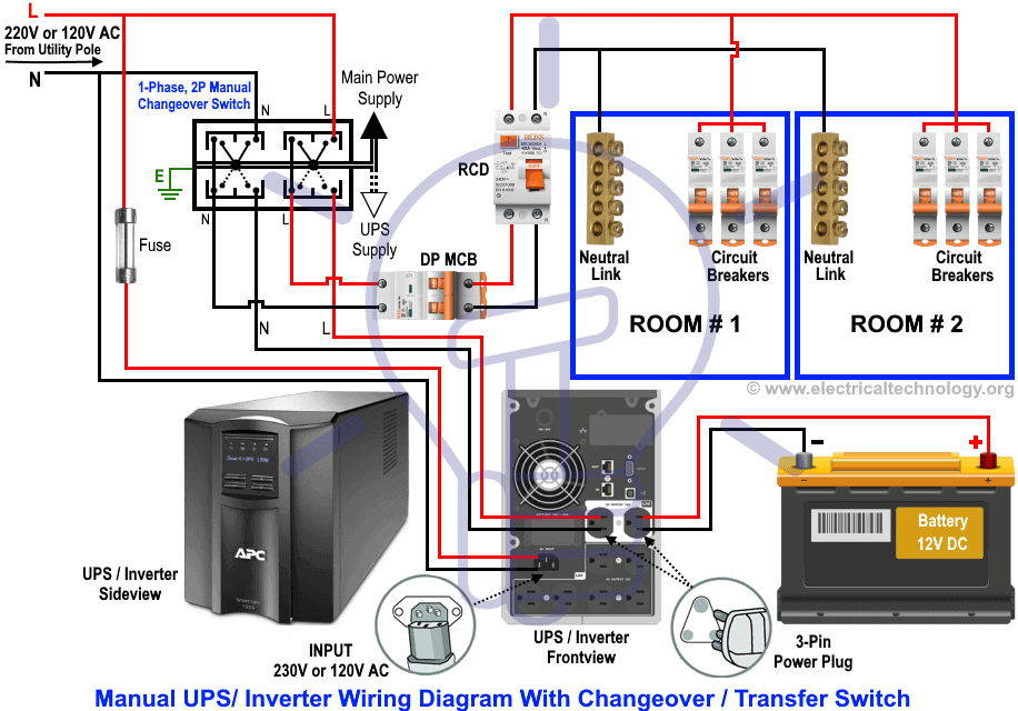
How to Wire Inverter with Manual Transfer Switch? (All Load)
Instead of partial load, you may connect and install the battery and inverter to the main board with the help of manual changeover switch as shown below. The working and operation of this method is same as mention above.
Click image to enlarge
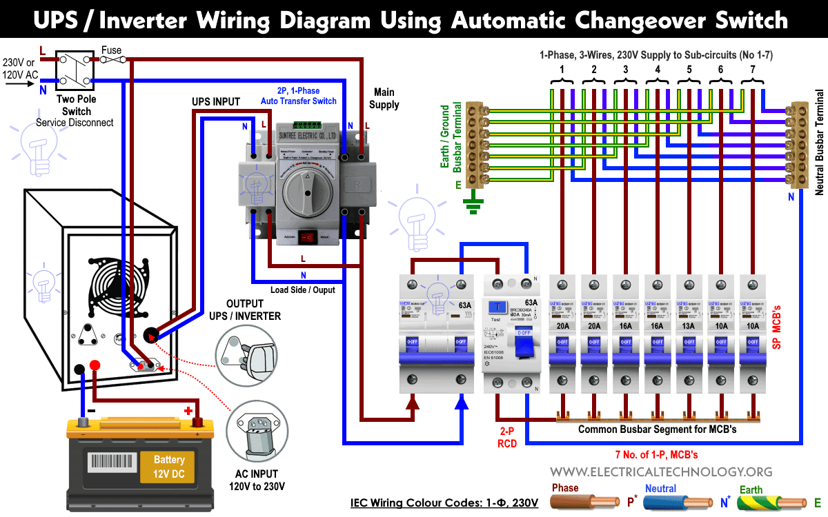
How to Wire UPS / Inverter with Automatic Changeover Switch?
This is the same wiring connection as mentioned above expect automatic transfer or changeover switch instead of manual.
In this case, the two pole automatic single phase changeover or ATS will transfer the power automatically from main to UPS and battery in case of battery. The rest of operation is same as above.
Click image to enlarge
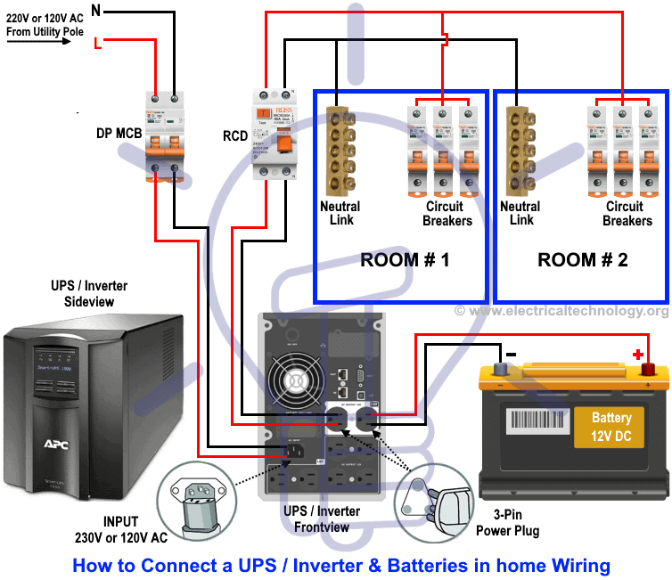
How to Wire Auto UPS without Changeover / ATS Switch?
In this case, you don’t need manual and even an automatic transfer or changeover switches for automatic operation of continuous power supply in case of power outage.
In this wiring system, the main power is connected to the Double pole (DP) MCB. Two wires as Phase and Neutral from the DP main switch is directly connected to the UPS as input while the Output of the UPS has been connected to the RCD (Residual Current Device) and other related single pole circuit breakers then. Load can be connected to the SP MCBs through switches.
In case of power failuer, the UPS will automatically supply the backup power of the batteries to the connected appliances. In case when utility power restores, the UPS will start to charge the battery as well as supply the main power to the whole load connected through main distribution board.
You may also read:
- Single Phase Electrical Wiring Installation in Home – NEC & IEC
- Single Phase Electrical Wiring installation in a Multi-Story Building
Click image to enlarge
Wiring Color Code:
We have used Red for Live or Phase , Black for Neutral and Green for Earth Wire in single phase. You may use the specific area codes i.e. IEC – International Electrotechnical Commission (UK, EU etc) or NEC (National Electrical Code [US & Canada] where;
NEC:
Single Phase 120V AC:
Black = Phase or Line, White = Neutral and Green/Yellow = Earth Conductor
IEC:
Single Phase 230V AC:
Brown = Phase or Line, Blue = Neutral and Green = Earth Conductor.
Note: Use 6 AWG (7/064″ or 16mm2) cable and wire size to connect the UPS to the main panel board.
General Precautions
- Disconnect the power source before servicing, repairing or installing electrical equipments.
- Use the proper cable in size with this simple calculation method ( How to determine the suitable size of cable for Electrical Wiring Installation)
- Never try to work on electricity without proper guidance and care.
- Work with electricity only in presence of those persons who has good knowledge and practical work and experience who know how to deal with electricity.
- Read all the instructions, user manuals, cautions and follow them strictly.
- Doing your own electrical work is dangerous as well as illegal in some areas.Contact the licensed electrician or the power supply company before practicing any change in electrical wiring connection.
- The author will not be liable for any losses, injuries, or damages from the display or use of this information or if you try any circuit in wrong format. So please! Be careful because it’s all about electricity and electricity is too dangerous.
If you are still facing difficulties to wire the UPS and batteries with changeover and ATS switches,, please leave a comment in the below comment box and I will be there to assist you more in details.
You may also read other Electrical Wiring Installation Tutorials.


It's a very very useful and easy to understand for non technical person.. Great design..<br /><br />Dear Wasim Bhai, God bless you for this, hope u must keep continue with this kind of technical advice…
Thanks a lot for your appreciation.<br />
WASIM BHAI wonderful work … plz keep uploading more diagrams like this<br /><br /><br />aswin
Thanks a lot Dear,,,, We will do our best…
Do yoo have diagram for ups and genset system just like hospital electrical system, thanks
We will post it soon…Keep touch in with us..
Excellent Explanation…
Thanks or appreciation..
great stuff with excellent explanation now i can say em proud of being PAKistani Just Because of u My Brother I Salute your work thumbs up from OMAN
like to know more on power savers and circuit breakers
good job wasim. dear all, do you have fire fighting circuit diagram? if have please share it with me.
I want to learn more on ATS, UPS and Genset connections! Any book that I can download to help me understand more and more…
Dear Wasim bhai,
Very easy and informative method for beginners.You explained us very well.
Thank you
thanks for more explanation i get the concept about it
Dear wasim, would u like 2 send me your whatsapp NO. I bill contact u and appreciate you there. You r a great man of this world. May ALLAH TALLA provide u a long life! My NO is 09797490325
Dear Sir,
I have a non automatic inverter and intend to configure a solar panels to it, Can you oblige to give a connection diagram?
Also if i purchase a hybrid inverter with an inbuilt mppt solar charger, do i need to buy an additional external mppt solar charging controller?
Is automatic ups wiring is possible for all UPS. If not , how to know whether we have to wire in manual mode or automatic mode. Kindly clarify.
more thank’s, it’s nice
Thank you for this very interesting article. In my situation I have a stand-alone pv system consisting of 15 X 180 watt panels,10X 12 volt batteries (linked to make 5 x 24 v batteries ) (which are now well and truly dead as a do-do) 5 charge controllers and a 5 kw inverter. I am now connected to the grid and haven’t used the pv system since the batteries died. Apart from the batteries, I assume all my other equipment is working correctly. Will it be possible for me to add a ATS as per your wiring diagrams, using the PV as primary source, then switching to the grid when the sun sets? and then will the system automatically switch to solar when the sun rises? This sounds interesting if it will work!!!!! I live in Cyprus with plenty of raw materials, sunshine.
Dear Support, I just need an advice from you on the following matter I have an inverter and grid supply at my home So currently inverter supply is directly connecting to the distribution circuits where neutral wire being same.In that setup I am not getting RCCB protection while inverter is on. Now what I need is to have an automatic change over box/ circuit where we can connect seperately the grid and inverter circuit, where Grid line fails it should switch to inverter circuit, As RCCB coming after that circuit I will get it’s protection even INVERTER IS ON Is this idea is acceptable and if yes is there any solution for that. Regards, Liju
Sir,
What is the mechanism, internal construction, operation of power transfer switch of UPS that can changeover its contacts in less than 8 milli seconds ? Also please post some image by brand / manufacturer? Please reply on my email. What you have shown here I am unable to digest.
Thanks & Regards,
Mukesh Kumar