Wiring Digital Twin Timer for ON/OFF Delay Operations in 120 and 240V Circuits
As the name suggests, a digital twin timer performs dual operations in a single circuit. It can be wired and configured for one-shot operation or a repeated ON/OFF delay mechanism. In today’s wiring tutorial, we will learn how to wire a twin timer to control 120V and 240V load circuits for ON and OFF delay operations.
Before going into details, let’s examine the internal wiring connections and terminals of twin timers, such as Inkbird twin timers, Omron DH48S-S, Sestos twin timers, H3CR-F solid-state twin timers, etc.
Related Posts:
- How to Wire One-Shot Timer using Twin Timer For Delay?
- How to Wire Twin Timer with Photo Eye Circuit for Time Delay?
8-PIN Twin Timer (DH48S): Base & Terminals Connections

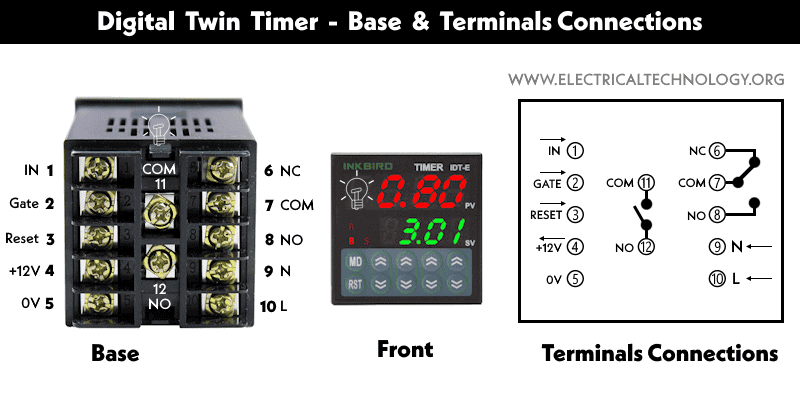
Digital Twin Timer – Base & Terminal Connections
Wiring Twin Timer for OFF-Delay
As a general setup, the power supply (120V-240V AC) is connected to the 2 and 7 terminals via Neutral and Line (Hot). The hot wire is connected to the 8 terminal through a jumper wire from 7. The load is connected to the 5-NC terminal of the twin timer.
When the timer is connected to the power supply, it activates, and the timer starts to count the preset time. When it reaches the predefined time interval (in seconds, minutes, or hours), its 5 – NC contact opens and closes with 6 – NO. This way, the light turns OFF.
When the power is disconnected from the timer, it deactivates and reactivates the sequence when power is restored to the timer circuit.

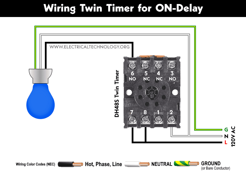
Wiring Twin Timer for ON-Delay
The wiring configuration for the ON-delay using a twin timer is the same as above, except the light bulb is connected to the 6 – NO terminal instead of the 5 – NC. Hence, the circuit operation is reversed, and the load will turn on after the delay time expires in the twin timer.
Related Posts:
- How to Toggle between Two Heat Pumps using 240V Twin Timer?
- How to Toggle Electric Water Heater Between 120V and 240V?
Wiring Twin Timer for Double Operations
As the twin timer has two timer functions, T1 (timer 1) and T2 (timer 2), the time settings in seconds, minutes, and hours can be set up for both circuits. Wire the circuit as shown in the following diagram. Now, let’s see how it works.

For example, the time setting for both light bulbs is 5 seconds (you may use other time setting based on the circuit requirement): 5 seconds of OFF-delay for the Blue light bulb connected to the 6 – NO terminal and 5 seconds of ON-delay for the Red light bulb connected to the 5 – NC terminal of the twin timer.
When the circuit is activated by providing a power supply of 120/240V AC to the timer, it will start counting. After counting for 5 seconds, the Blue light bulb will turn ON, and the red light bulb will turn OFF.
The Red push button is used to reset the circuit. For instance, when the timer starts counting the predefined time period, if the operator presses the red push button, the timer will reset and start the time from the beginning, i.e., from zero.
If the operator presses the Green push button, it will pause the circuit, meaning the timer will stop counting the time until the green push button is released.
below are some additional circuit and wiring diagrams using Twin timer for repeated cycle and one-shot operations.
Related Posts:
- How to Control 120V & 240V Water Heater using ST01 Timer and Contactors?
- How to Wire ST01 Timer with Relay & Contactor for 120V/240V Motors?
Wiring Twin Timer in Repeated Cycle Mode:
For more details, you may see a comprehensive article on how to wire a twin timer for repeated cycle operation of motors.

Wiring Twin Timer For One-Shot Operation:
A detailed post has been published on wiring a twin timer for one-shot operation of recirculation pump.

Related Posts:
- How to Wire Twin Timer for Repeated ON-Delay in Cycle Mode?
- Wire Twin Timer in Repeat Cycle & One-Shot Mode for 120V/240V Motors?
- How to Reduce Runtime of Air-Conditioner During Peak Hours?
- How to Wire Multifunction ON/OFF Delay Timer for 120V/240V Motors?
- How to Wire ON-Delay Timer for 120V and 240V Load Circuits?
- How to Wire OFF-Delay Timer for 120V and 240V Load Circuits?
- Difference Between ON Delay and OFF Delay Timer
- How to Wire ON/OFF Delay Timer for AC & DC Loads – 230V & 24VDC
- Automatic & Manual Control of 3-Phase Motor Using Delay Timer
- Automatic ON/OFF Circuit Using Two 8-PIN Timers for 1 & 3-Φ Load
- How to Wire AH3 OFF-Delay Timer and Relay with Boiler Fan?
- How to Reverse Operation of Photo Eye using ST01 Timer?
- How to Wire ST01 Timer for Dusk-Dawn On-Delay Light Control?
- How to Wire Spring Wound Timer with LYS Rely for ON/OFF Delay
- How to Wire Remote Control Countdown Timer?
-
 How to Install a Home and Away Wireless Smart Switch
-
 How to Install a Wire-Free Smart Dimmer Anywhere Companion
-
 How to Wire a Smart Wireless Switch and Anywhere Companion
-
 Wiring a Smart Dimmer Switch Companion with a Digital Dimmer
-
 How to Wire a Digital and Wi-Fi Smart LED Dimmer Switch
-
 How to Wire a Smart Switch Companion with a Smart Switch