Automatic ON/OFF Circuit Using Two 8-PIN Timers for 1 & 3-Φ Load
Automatic Start & Stop Circuit for 1-Phase Load and 3-Phase Motors Using two 8-PIN Timers
Automating the operation of 3-phase motors or single phase load in industrial setups brings efficiency and convenience. An Automatic Stop and Run circuit, also known as Auto ON/OFF, enables the seamless control of a 3-phase motor’s start and stop cycles. In this article, we will show how to design an automatic ON/OFF circuit for both single phase and three phase load using two 8-PIN timers with power, control and wiring diagrams
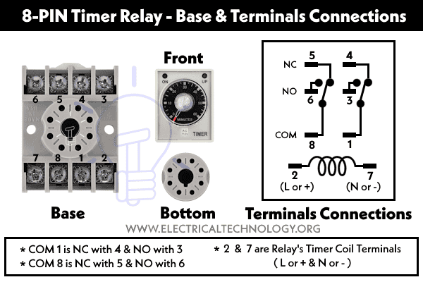
8-PIN Timers Relay
As the name suggests, 8-PIN timers have 8 terminals which offer different switching functionality. The Omron H3CR (or AH3, SA3PA-B, H3BA etc.) timer typically has a total of 8 terminals. These terminals are labeled and serve various functions related to timer control and connections. Here’s a breakdown of the terminal functions:
- 2 – Supply Voltage (+ or L)
- 7 – Supply Voltage (- or N)
- 3 & 6 – NO (Normally Open) Contact Terminal
- 4 & 5 – NC (Normally Closed) Contact Terminal
- 1 & 8 – COM (Common) Contact Terminal
Connections of 8-Pin Timer Terminals:
As shown in fig, the 8-pin timer relay terminals are interconnected with the following pin configuration:
- Pins 2, 7: Relay’s Coil ( + or L & – or N to energize the coil)
- (COM) 1 is (NC) with 4 and (NO) with 3.
- P(COM) 8 is (NC) with 5 and (NO) with 6.
Auto ON/OFF Circuit
The Auto ON/OFF circuit enhances the control of 3-phase motors or single phase load by allowing the motor to start and stop automatically based on predetermined time intervals. This eliminates the need for constant monitoring and intervention, streamlining the operation of equipment such as pumps, conveyors, and fans.
Related Posts:
- Automatic & Manual Control of 3-Phase Motor Using Delay Timer
- Wiring of DOL Starter for Automatic / Manual Control Using Digital Timer
Components Required
To create an Auto ON/OFF circuit using two 8-PIN timers, the following components are needed:
- 2 Nos. of 8-PIN Timer Relay
- Contactor
- Thermal Overload Relay
- 2P-MCB and 3-P MCCB
- 1 NO ON/OFF Switch
- Single Phase & Three Phase Supply
- Wires & Cables
- Three-Phase Motor or a light bulb (optional as a load)
Wiring, Power and Control Circuit
Wiring & Control for 1-Phase Load

Wiring & Control for 3-Phase Load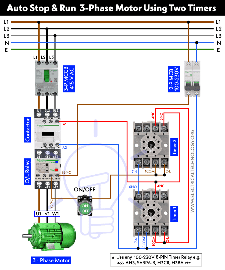
To wire an automatic Start and Stop circuit for both single phase and three phase load, follow the simple steps given below according to the given power and control diagrams.
Three Phase Load
- For a three-phase load, such as motors, connect the 415V AC three-phase power supply from the 3-P MCCB to the Contactor’s L1, L2, and L3 terminals, then to the Overload Relay, and finally to the 3-Phase motor’s U1, V1, and W1 terminals. Note that using a motor as a load is optional; various types of three-phase or single-phase loads can be connected through the power circuit.
- Connect the phase (line) wire from the 2P MCB to the 95NC terminal of the Overload (O/L) relay. Link the wire from 96NC on the O/L relay to the ON/OFF switch, and from there, connect it to terminals 1COM and 2-L of the 8-PIN timer 2.
- Join the 4-NC wire from timer 2 to the 1COM and 2-L terminals of timer 1. Attach the 3-NO wire from timer 2 to the 4-NC of timer 2 and the A2 terminal of the contactor.
- Establish a jumper wire connection: link timer 1’s terminal 6-NO to the 7-N terminal of timer 2, and then connect it to the A2 terminal of the contactor.
- Lastly, ensure the proper grounding of the motor, DOL starter, and control circuit to ensure safety.
Single-Phase Load
- All steps remain the same, except for connecting a 100-230V light bulb to the line and neutral. In this case, both wires are connected to the A1 and A2 terminals of the contactor, unlike the three-phase load setup.
- To complete the single-phase load configuration, wire both 8-PIN timers as previously described, and connect the single-phase load (light bulb) to the 7-NC terminal of Timer 1. The common wire should be connected to terminals 3-NO (Timer 2) and 4-NC (Timer 2).
Operation of the Auto ON-OFF Circuit Using 8-PIN Timers
- When we switch the circuit ON by pressing the ON/OFF button, the normally open (NO) terminals become closed (NC) terminals, and vice versa.
- Consequently, the phase supply flows through 1-COM of timer 1 to the 4-NC of timer 2. This action triggers the activation of timer 1, initiating the countdown of the preset value.
- As timer 1 runs its cycle, the supply is routed to the load via timer 2.
- Upon timer 2 reaching its preset value, it switches OFF, completing the circuit via timer 1.
- The same process occurs continuously, meaning that the load automatically switches ON and OFF alternately due to the actions of both timers within the specified time limits. It’s important to note that both timers cannot be connected to the load simultaneously, because both timers are interlocked.
- Configure the first timer with the desired time interval for motor operation or light bulb (start time). Configure the second timer with the desired time interval for motor stoppage or disconnecting the single phase load (stop time).
- The Start and Stop button can be used for manual operation or to disconnect the power supply to the circuit.
Related Posts:
- How to Wire 8-PIN Relay for Holding or Latching Circuit?
- ON / OFF 3- Phase Motor Using 8-PIN Relay and DOL Starter
- How to Wire 11-PIN Relay for Interlocking and Holding Circuits?
- ON / OFF 3- Phase Motor Using 11-PIN Relay and DOL Starter
- How to Wire 14-PIN Relay for Holding or Latching Circuit?
- ON / OFF 3- Phase Motor Using 14-PIN Relay and DOL Starter
- How to Control a Three-Phase Motor Using Solid-State Relay?
- Sequential Motor Control Circuit Using ZEN Programable Relay
- Reverse-Forward Star/Delta Starter for Three Phase Motor using Timer
- Automatic Star-Delta Starter using Timer – Power, Control & Wiring Diagrams
- How to Wire ON/OFF Delay Timer for AC & DC Loads – 230V & 24V
- Difference Between ON Delay and OFF Delay Timer


thnx so much