How to Wire ST01 Timer with Relay & Contactor for 120V/240V Motors?
How to Control 120V & 240V Pump Motor using ST01 Timer, Relay and Contactors?
As a versatile component, the ST01 timer can be used to control the sequential operations of LED, CFL, halogen light bulbs, and other inductive loads, e.g., motors, for both 120V and 240V circuits. In today’s wiring tutorial, we will show how to wire and control 120V or 240V motor using the ST01 timer, with the help of contactor coils and relays.
The ST01 timer is rated for 15-ampere circuits and equipped with a CR2 battery. It doesn’t need a neutral wire and can be easily fixed in an ordinary switch box.
It can be used for both 120V and 240V circuits for a maximum distance of 100 ft (30 meters). General 240V load points can be directly connected to the timer. For heavy loads and motor pumps, a 2-pole contactor (40-60A) or relay (LY2, LY3, LY4, R4 30A DPDT) is recommended.
Use a 10-15 amp Bussmann or inline fuse on one of the hot wires to the timer to protect the timer from high amperage in the contactor circuit.
Wiring Timer with 120V Motor Using Relay
As shown in the wiring diagram, a 30A, 120V coil relay is used to wire with both the ST01 timer and a 120V single-phase motor. It is because the motor amperage exceeds the ampere rating of timer (15A). If load is equal or less than 15A, you may connect the load directly to the timer.
The circuit can be modified to override the proposed operation of the motor. As the red wire is not used in the circuit, simply cap-off (put a wire nut and fix in the box).
Click image to enlarge

Connect a 15A inline fuse to the black wire of the timer to protect the timer from the heavy current of the relay circuit.
Simply wire the entire circuit as shown in the figure and program the time setting in the timer according to your needs. This way, it will operate and turn ON/OFF automatically based on the preset time.
Related Posts:
- How to Toggle between Two Heat Pumps using 240V Twin Timer?
- How to Toggle Electric Water Heater Between 120V and 240V?
Wiring Timer with 120/240V Motor Using Relay
The purpose of this circuit is same except it can be used for both 120V and 240V circuits. As we have used 30A, 24V DPDT coil relay instead of 120V AC, an additional 120V/24V step-down transformer or adapter is needed.
For 120V circuits, use black and white as Hot and Neutral wires respectively. For 240V circuits, use black and red for Hot 1 and Hot 2 wires respectively. The rest of the circuit and operation is same as above.
Click image to enlarge

Related Posts:
- How to Wire ST01 Timer for Dusk-Dawn On-Delay Light Control?
- How to Reverse Operation of Photo Eye using ST01 Timer?
Wiring Timer with 120V/240V Motor Using Contactor
The fallowing wiring diagram shows a 120V or 240V single phase motor is controlled via contactor and ST01 timer.

After wiring the circuit according to the figure below, configure the timer for automatic ON and OFF operation based on specified time intervals. Don’t forget to add a fuse on Line (in 120V) or a Hot to the timer (in 240V) circuit to protect the digital programable timer from high current.
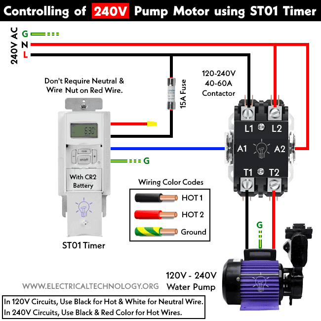
- In a 120V motor circuit, use black for the hot wire and white for the neutral wire.
- In a 240V motor circuit, use black for hot-1 and red for hot-2 wires.
Related Posts:
- How to Wire ON-Delay Timer for 120V and 240V Load Circuits?
- How to Wire OFF-Delay Timer for 120V and 240V Load Circuits?
- How to Wire AH3 OFF-Delay Timer and Relay with Boiler Fan?
- How to Wire Remote Control Countdown Timer?
- Difference Between ON Delay and OFF Delay Timer
- How to Wire ON/OFF Delay Timer for AC & DC Loads – 230V & 24VDC
- Automatic & Manual Control of 3-Phase Motor Using Delay Timer
- Wiring of DOL Starter for Automatic / Manual Control Using Digital Timer
- Automatic ON/OFF Circuit Using Two 8-PIN Timers for 1 & 3-Φ Load
- How to Wire Twin Timer with Photo Eye Circuit for Time Delay?


