How to Wire OFF-Delay Timer for 120V and 240V Load Circuits?
Wiring the AH3-3 OFF-Delay Timer for 120V and 240V Circuits
Timers are essential components in various residential, industrial and automation applications. They help control the timing of processes and equipment, ensuring that actions occur in a precise sequence or for a specified duration. One commonly used timer is the AH3-3 Timer, which can be wired for OFF-Delay, ON-Delay or as a relay which allows you to control the delay time before a connected load turns off or on. In this article, we will guide you how to wire an AH3-3 timer to control OFF-Delay operation for both 120V and 240V load circuits.
What is AH3 Timer?
The AH3 Delay timer is a versatile and reliable timer that can be used in a wide range of applications. It is designed to delay the de-energization of a load (e.g., a motor, relay, or solenoid) after a triggering input is removed or released. The timer is available in different voltage ratings, including 120V and 240V AC and 24V DC etc., to suit various power supply requirements.
Timers like AH3-3, H3CR, H3BA ,SA3PA-B etc. can be used for different applications such as OFF-Delay, ON-Delay and relay switching or all of them at once.
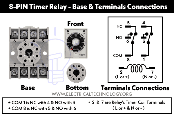
Following are the labels of terminals printed on AH3 timer nameplate.
- Terminal 2: Supply Voltage – Phase (L or +)
- Terminal 7: Supply Voltage – Neutral (- or N)
- Terminals 1 and 8: Common (COM) contacts
- Terminals 3 and 6: Normally Open (NO) Contacts
- Terminals 4 and 5: Normally Closed (NC) Contacts
Before proceeding with the wiring instructions, it’s crucial to understand the timer’s key components:
- Control Voltage: This is the voltage that powers the timer and controls its operation. It can be either 120V or 240V AC or 24VDC connected to the 2 and 7 terminals, depending on your application.
- Delay Adjustment: The timer allows you to adjust the OFF/ON delay time using a potentiometer or dial. This setting determines how long the load will remain energized after the trigger signal is removed.
- Trigger Input: The timer starts counting down its delay time when it receives a trigger input. This input can be a momentary switch (two-way, three-way, pushbutton) or any other signal that you want to use as a trigger.
- Load Output: The load output is where you connect your load to the NO or NC terminals (depends on the circuit deign and requirement), such as a motor, attic fan or relay further connected to the another load. It remains energized for the specified delay time after the trigger signal is removed.
Terminals Connections of AH3-3 Timer:
The following fig shows the base terminals and its pins connections of AH3 relay timer.
- Pins 2 & 7: Relay’s Coil (Phase & Neutral for AC or “+” & “–” for DC respectively to energize the relay timer coil.)
- 1 (COM) is Normally Closed (NC) with 4 and Normally Open (NO) with Terminal 3.
- 8 (COM) is Normally Closed (NC) with 5 and Normally Open (NO) with Terminal 6.
Feature and Rating of the Delay Timer
- OFF-delay means (and used) when you need to activate an appliance immediately for a specific given time and then shut it down automatically after the specified delay time expires.
- ON-delay means (and used) when you need to activate an appliance after a specific time. The appliance will be off during the specified time. When the delay time express, the load circuit will be activated. For more details, read the difference between ON-Delay and OFF-Delay Timer.
- Common setting for time is 0-60 minutes approximately
- For 120V load circuits, it can be wired for 6 amperes.
- For 240V load circuits, it should be wired maximum for 3 amps.
- The max load of (120V x 6A or 240V x 3A = 720W) e.g. make sure the load doesn’t exceed the 1/4 hp of load i.e. recirculation pumps, attic fans, water pump etc. (rated at 1/4 hp, 1/3 hp 1/2 hp) should be connected to the timer. This is because the inductive load such as motor takes high current in the initial starting stage.
How to Wire AH3-3 OFF-Delay Timer for 120V & 240V Circuits?
Follow these steps to wire the AH3-3 OFF-Delay Timer for a 120V or 240V single-phase load points:
- Safety First: Before you start, ensure that the power to the circuit is turned off. Safety should always be your top priority when working with electrical components. If still unsure, contact a licensed electrician to do it for you.
- Determine the Voltage: Decide the load circuit (either you need it for 120V or 240V load circuits) and confirm that your AH3-3 timer is rated for 120V or 240V operation. Verify this information by checking the product label or datasheet.
- Connect Control Voltage: Connect the phase (or Line 1) terminal of the 120V or 240V power supply to the (2) L terminal (Line) on the timer and the 7 terminal to the N terminal (Neutral).
- Connect Trigger Input: Connect your trigger input source (e.g., a switch, pushbutton) to the start terminal on the timer. For example, a phase line through a 2 or 3-Way switch to the 2nd terminal of the timer. This is used to control the input signal to operate the timer.
- Connect Load: Connect the load (e.g., a motor, attic fan, light bulb, buzzer) between the COM (Common) terminal and the NO (Normally Open) or NC (normally closed) terminal on the timer. It depends on the circuit deign and requirements either ON-Delay or OFF-Delay operations.
- Adjust Delay Time: Use the timer’s adjustment dial to set the desired delay time for ON/OFF Delay operation.
- Power On: Turn on the power supply, and the timer should start operating according to the set delay time. When the trigger input (switch) is released, the load will remain energized for the specified delay period before turning off.

Good to Know: Wiring the AH3-3 timer for a 240V load circuit is similar to the 120V setup but with the appropriate voltage rating and wiring the second line wire to the 7 number of terminal instead of Neutral in 120V circuit.
In simple words.
Timer Connection in 120V
- Line (Phase) to terminal # 2
- Neutral to Terminal # 7
Timer Connection 1n 240V
- Line 1 to terminal # 2
- Line 2 to Terminal # 7
Wiring the AH3-3 OFF-Delay Timer using 2-Way Switch
In the following basic wiring diagram, we have used a single-pole switch to control the attic/exhaust fan operation through OFF-delay mechanism using AH3-3 timer. You may have noticed a fuse and fuse holder on phase wire to the two-way switch. It is because to protect the 18-gauge wire incase of overload or short circuit.
Suppose the circuit is fed-up by 20A breaker while we know that the 18-gauge wire is not suitable for 20 amps (12-gauge is rated for 20A). If a short circuit happens on 20A circuit, the whole 20-A will go through the 18-gauge wire used for switch. This may lead to overheat and cause fire. To prevent this scenario, use 5-10A fuse on anywhere on18-gauge small wire to the timer.
Click image or open in new tab to enlarge

You may use a single-pole switch (a single-pole (two-way) switch like a rocker) instead of 3-way switch. If you do:
- When the single-pole switch is OFF, the load circuit will remain OFF.
- Please keep in mind that the switch must be turned OFF and then turned ON to reset the timer.
Wiring the AH3-3 OFF-Delay Timer for Pump using 3-Way Switch
In the following wiring circuit, we have used a 3-way switch with a water pump (which can be any load such as an attic fan, light bulb, buzzer, etc.) for OFF-delay operation.
Click image or open in new tab to enlarge

Any position of the three-way switch (either UP or DOWN) will activate the circuit, i.e., the timer will activate, and the load circuit will turn OFF after the delay time set on the timer. Using the 3-way switch:
- When the switch position is UP, the delay operation starts
- When the switch position is DOWN, the delay operation starts.
- The load circuit will switch-off automatically when the specified delay time expires.
- When the OFF-delay operation ends, the timer resets to the initial state.
Wiring the AH3-3 OFF-Delay Timer using 3-Way Switch & Pushbuttons
We have modified the above wiring circuit by adding additional NC (normally closed) push buttons for remote control operation. This means the circuit of recirculation pump remain ON continually until an operator presses the push button, which will break the power supply to the circuit.
Conversely, NO (normally open) push buttons (similar to doorbells, etc.) will activate the circuit when you press them and break the circuit when you release the pressure.

As the circuit is always ON (in either the UP or DOWN position of the three-way switch), when the power supply is interrupted to the circuit, it restores itself to its initial stage. The three-way switch is the primary control, while the push buttons are installed at different locations for remote operation. You may add multiple NC push buttons to control the circuit from various remote locations.
Wiring the AH3-3 OFF-Delay Timer using Only Pushbuttons
Let’s modify the above circuit diagram to make it even simpler by removing the 3-way switch. This way, the AH3 timer is controlled only by NC (normally closed) push buttons. We have used a light bulb as an example load in the circuit, but you may add other appliances such as an attic fan or recirculation pump for a water heater, etc.

You may install as many NC push buttons in different locations (e.g., each bathroom). Here is the working and operation of the circuit:
- When the operator presses the ON button, the circuit activates, and the delay timer starts to count.
- The light bulb or recirculation pump starts and runs.
- Hot water from the water heater circulates to each bathroom.
- When the delay time comes to an end, the recirculation pump (or any other connected load) switches OFF.
- When the operator presses the NC push button, the circuit breaks, cutting power to the timer, and the pump stops immediately.
- When the operator releases the NC push button, the circuit connects again, providing power to the timer. The delay timer starts to count down, and the recirculation pump turns ON once again.
- When the delay time period ends, power is still ON at the timer, but the connected load to the timer is OFF.
Related Posts:
- How to Wire AH3 OFF-Delay Timer and Relay with Boiler Fan?
- How to Wire Remote Control Countdown Timer?
- How to Wire Spring Wound Timer with LYS Rely for ON/OFF Delay
- How to Wire ST01 Timer for Dusk-Down On-Delay Light Control?
- How to Wire Twin Timer with Photo Eye Circuit for Time Delay?
- Difference Between ON Delay and OFF Delay Timer
- How to Wire ON/OFF Delay Timer for AC & DC Loads – 230V & 24VDC
- Automatic & Manual Control of 3-Phase Motor Using Delay Timer
- Wiring of DOL Starter for Automatic / Manual Control Using Digital Timer
- Automatic ON/OFF Circuit Using Two 8-PIN Timers for 1 & 3-Φ Load


