What Happens if You Interchange the Line and Load Terminals on a GFCI Outlet?
In the case of a GFCI breaker, installation is straightforward because it snaps onto the hot busbar in the main panel in the same manner as a standard circuit breaker. However, the situation is different with a GFCI outlet, as its internal design differs from that of a standard receptacle. For this reason, a GFCI outlet must be wired correctly. Mixing up the LINE and LOAD terminals can render the device ineffective and may leave the circuit unprotected, increasing the risk of electric shock.
In this article, we will explain the difference between the LINE and LOAD terminals of a GFCI outlet, demonstrate the correct wiring method, and discuss the potential hazards and consequences of reversing the terminals (connecting LINE to LOAD and vice versa).
What is a GFCI Outlet?
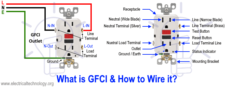
A GFCI (Ground-Fault Circuit Interrupter) outlet is a protective electrical receptacle designed to reduce the risk of electric shock by monitoring the balance of current flowing between the hot and neutral conductors. If the device detects a small (4-6mA) leakage current to ground, it quickly disconnects power to the circuit.
GFCI outlets are required to installed in areas exposed to moisture, such as bathrooms, kitchens, garages, basements, and outdoor locations, where the likelihood of ground faults is higher as per NEC – 210.8(A)(1) through (A)(11).
GFCI Line and Load Terminals
Line Terminal
The Line terminals are the incoming power supply from the main panel to the GFCI. It is the wiring connection that receive the HOT (Phase) and Neutral conductors directly from the GFCI circuit breaker or power source. These terminals must be connected correctly for the GFCI to operate at all.
Good to Know: In Line terminals wiring, the hot (line) conductor (black wire) connects to the brass-colored screw, while the neutral (line) conductor (white wire) connects to the silver-colored screw.
Load Terminal
As the name suggests, Load terminals are optional outgoing connections used to supply power to downstream receptacles or devices while extending GFCI protection to them. When devices are connected to the Load side, they are protected against ground faults by the same GFCI.
Good to know: In LOAD terminals of a GFCI, the hot conductor (black wire) connects to the brass-screw, and the neutral conductor (white wire) connects to the silver screw. These LOAD terminals supply power to downstream branch-circuit receptacles or other load points to be GFCI protected.
Wiring Connections of GFCI Line & Load Terminals
✔ – Only GFCI Outlet Protection
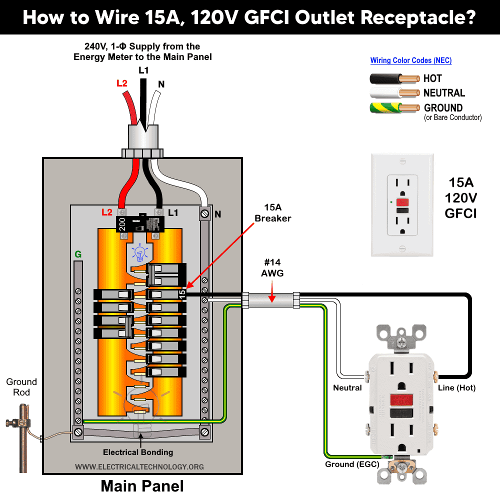
The following diagram shows the wiring of a dedicated 15A, 120V GFCI receptacle. The Line terminals of the GFCI are supplied directly from a 15A, 1-pole breaker in the main panel. Because only the Line terminals are used and no downstream Load connections are made, both receptacles on the GFCI outlet are protected by the built-in GFCI mechanism.
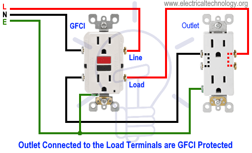
✔ – Both GFCI Outlet & Downstream Protection
The following diagram illustrates the wiring of a 15A/120-V GFCI outlet with a standard receptacle installed downstream of the GFCI. Since the standard 15A receptacle is connected to the Load terminals of the GFCI, both the GFCI outlet and the downstream standard outlet are protected by the GFCI.
✔ – Only GFCI Outlet without Downstream Protection
The following diagram shows the same 15A – 120V GFCI and standard outlet wiring, except the standard 15A receptacle is connected to the Line terminals of the GFCI. Therefore, only the GFCI outlet itself is protected, and the downstream standard outlet is not GFCI-protected.

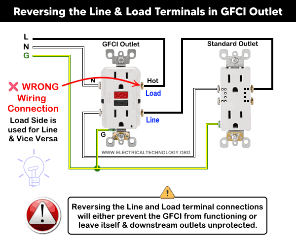
✗ – Wrong Connection – No Protection at All
The following diagram shows the wrong wiring connection of 15A – 120V GFCI and standard outlet where the Line and Load connections of GFCI are reversed. In other words, the branch-circuit conductors from the breaker are connected to the LOAD terminals of the GFCI, while the downstream load conductors are connected to the LINE terminals of the GFCI. This wiring arrangement is completely incorrect. In this case, both the GFCI outlet itself and downstream connected standard outlets are not GFCI protected and may prevent the GFCI from operating properly.
Reversing or mixing Line and Load connections will either prevent the GFCI from functioning or leave GFCI outlet itself and connected downstream outlets unprotected, which is why manufacturers clearly mark these terminals on the back side of outlet.
Identification of Line and Load terminals in a GFCI Outlet
GFCI outlets and breakers are labeled “LINE” and “LOAD” on the back cover side. Mostly, the upper side screws are used for Line and the lower side screws are used for Load. If not sure, refer to the user manual for clear diagrams provided with the product from manufacturers.
- The Line terminals are the incoming power terminals that connect from the breaker or main supply to the GFCI.
- The Load terminals are used to provide GFCI protection to downstream outlets and fixture.
Another effective way to identify the Line and Load terminals is by using a non-contact voltage tester. To do this, first disconnect all loads connected to the device. Then, with the power still on at the breaker, test each wire with the tester. The wire that detects voltage is the Line (incoming power), while the wire that shows no voltage is the Load (outgoing to the downstream devices)
FAQs
What happens if you interchange the Line and Load terminals?
If you swap the wires i.e. connect the supply to the Load terminals instead of the Line terminals, the GFCI outlet will not provide power correctly, may fail to reset, or lose GFCI protection. In some cases, it could appear to work but downstream outlets may not be protected.
When to use the Line terminals?
Use the Line terminals for incoming power from the breaker or main panel. This is mandatory for the GFCI device to function correctly. If you want additional Non GFCI-protected circuit(s), you may wire it through the line wires.
When to use the Load terminals?
Use the Load terminals only if you want to provide GFCI protection to additional outlets downstream of the GFCI outlet. Do not connect the incoming supply to these terminals.
How many devices can I connect to the Load terminal of GFCI device?
While you can wire multiple outlets downstream from a GFCI receptacle, it is good practice to limit the total connected load to no more than 8–10 devices, each rated at 1.5 A, on a 15 A GFCI circuit. In no case should the combined rating or expected load of all downstream devices exceed the 15 A rating of the GFCI receptacle or the circuit breaker protecting it.
What is the correct and incorrect way of connecting Line and Load terminals in a GFCI device?
- Correct: Incoming hot and neutral wires from the breaker connect to the Line terminals. On the other hand, downstream outlets, if any, connect to the Load terminals.
- Incorrect: Reversing supply wires to the Load terminals or connecting downstream outlets to Line terminals (if not intended) without supply to Line can cause malfunction or loss of protection.
Is there a chance in a GFCI breaker to swap the Line and Load terminals similar to a GFCI outlet?
No. GFCI breakers are installed at the panel, and the Line connection is fixed at the breaker bus. Swapping Line and Load is not applicable because the breaker senses the current through the hot wire directly, and downstream connections are already protected via the panel.
Precautions:
- Ensure correct polarity by verifying the Line and Load terminals when installing a GFCI. In other words, connect the wires to the proper side of the outlet to ensure correct and reliable operation.
- Only one GFCI or AFCI device should be installed per circuit. Installing more than one may cause nuisance tripping.
- A GFCI circuit breaker protects the entire circuit, while a GFCI outlet can be installed to protect additional outlets, switches, and downstream devices.
- There is no need to install an additional GFCI outlet if the circuit is already protected by a GFCI circuit breaker.
- For proper operation, a GFCI must be correctly grounded. Without proper grounding, it may not trip instantly but will still provide protection before serious damage or electric shock occurs.
- Both 15A and 20A GFCI outlets can be wired using either back-wiring or side-wiring methods.
- Tighten the screw terminals to 16 lbf·in (1.8 Nm) or follow the torque specification marked on the receptacle.
- Certain devices, such as power-vented water heaters, should not be connected to a GFCI, as it may interfere with proper circuit operation.
- The Test and Reset buttons on a GFCI are primarily for testing purposes. The GFCI should always be tested before final use to ensure it is functioning correctly.
- Use #14 AWG wire for 15A circuits and #12 AWG wire for 20A circuits.
- 15A and 20A GFCI outlets should only be installed on 15-20A and 20A circuits, respectively. They must not be used with 30A or mismatched breakers.
Warning:
- Always turn off power first: Switch off the main circuit breaker at the main panel and verify that power is OFF (using a voltage tester) before beginning any electrical work. Working on live wires can result in serious injury or death.
- If you are not confident in following wiring diagrams or performing the installation safely, contact a licensed electrician. Electrical work must comply with local codes (such as the National Electrical Code in the US).
- Electricity is extremely dangerous. The information provided here is for general guidance only. The author and any associated parties assume no liability for any losses, injuries, damages, or other consequences arising from the use or misuse of this information. Always prioritize safety and consult a qualified professional for electrical work.
Resources:
Comparison
- Difference Between GFCI and Circuit Breaker
- Difference Between GFCI and AFCI
- Difference Between 15-Amp and 20-Amp Outlet?
- Difference Between NEMA 14-50 Standard Vs EV Receptacle
- Difference Between Socket, Outlet and Receptacle
- Difference Between 1-Pole and 2-Pole Breakers
- Difference Between EGC and GEC in Electrical Grounding
Related GFCI Wiring Tutorials
- How to Wire 1-P & 2-P, 1-Phase & 3-P, 3-Phase GFCI Breakers
- How to Wire a 1-Pole GFCI Breaker
- How to Wire a 2-Pole GFCI Breaker
- How to Wire a 3-Phase, 3-Pole GFCI Breaker
- How to Wire an AFCI Breaker?
- How to Wire a Smart GFCI Breaker
- How to Wire Smart AFCI/GFCI Breaker
- How to Wire a GFCI Outlet – Wiring a GFCI Receptacle
- How to Wire Wi-Fi Smart GFCI Outlets
- How to Wire GFCI Combo Switch and Outlet
- How to Wire an AFCI Outlet?
- How to Wire an Outlet Receptacle?
- How to Wire a 1-Pole Breaker
- How to Wire a 2-Pole Breaker
- How to Wire a 3-Pole Breaker
- How to Wire a Smart Breaker
Related Posts:
- Why Do We Need a GFCI & How Does it Protect During Faults?
- How Do GFCI and Standard Breakers Respond to Ground Faults?
- How to Find the Number of Outlets on a Single Circuit Breaker?
- What is the Difference Between 15-Amp and 20-Amp Outlet?
- How to Find Voltage & Ampere Rating of Switch, Plug, Outlet & Receptacle
- Can You use a 15A Outlet on a 20A Circuit and Vice Versa?
- What Happens if You Use a 120V Device on 240V & Vice Versa?
- Can I Use a 240V Breaker on a 120V Circuit and Vice Versa?
- Ground Terminal Up or Down: Which Way Should Outlets Face?
- What Do the Green Dot or Orange Triangle Outlets Mean?
- What Do the Different Colors of Electrical Outlets Indicate?
- Why are Outlets and Receptacles in Hospitals Upside Down?
- How to Size a Load Center, Panelboards and Distribution Board?
- How to Determine the Number of Circuit Breakers in a Panelboard?
- How to Find the Proper Size of Circuit Breaker? Breaker Size Calculator & Examples
- How to Find The Suitable Size of Cable & Wire for Electrical Wiring Installation?
- Why is the Neutral Prong or Slot Wider on a Plug or Outlet?
- What Will Happen If You Connect a Male-to-Male Plug Between Outlets
-
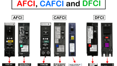 Difference Between AFCI, CAFCI, DFCI and GFCI?
-
 Can You Use a 2-Pole Breaker Instead of a 1-Pole Breaker
-
 What is the Life Expectancy of a Circuit Breaker?
-
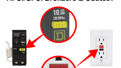 What Happens When You Press TEST and RESET on a GFCI
-
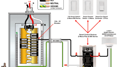 Wiring Z-Wave Smart Switch, Dimmer & Fan Speed Controller
-
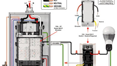 How to Wire a Smart Switch in a 120/240V Load Center