How to Wire 1-P & 2-P, 1-Phase & 3-P, 3-Phase GFCI Breakers
Wiring Installation of 1-Pole and 2-Pole, Single-Phase and 3-Pole, 3-Phase GFCI Circuit Breakers with & without Neutral
A Ground-Fault Circuit Interrupter (GFCI) is a safety device designed to protect people from electrical shock by monitoring the electrical current flowing through a circuit. It detects imbalances between the hot and neutral wires, which can indicate a ground fault where electricity is leaking out of the circuit.
If a ground fault is detected, the GFCI quickly cuts off the electrical power to prevent shock and potential electrocution. GFCIs are commonly installed in areas with higher risk of electrical hazards, such as bathrooms, kitchens, and outdoor spaces.
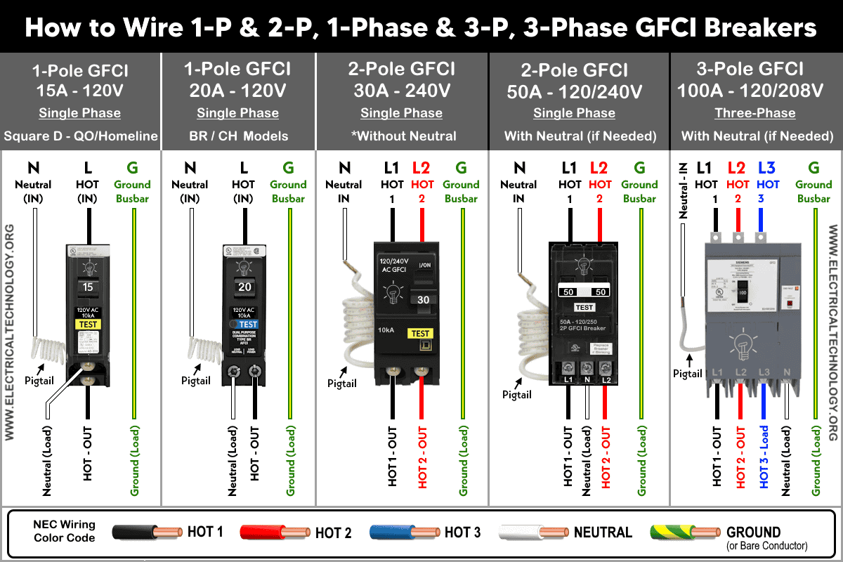
The following fig shows the different wiring connections of 1-Pole, 2-Pole and 3-Pole GFCI breakers with Neutral and without Neutral.
Click image or open in a new tab to enlarge
GFCI and RCD or RCCB are Same.
In North America, it is commonly known as GFCI (Ground Fault Circuit Interrupter) or GFI (Ground Fault Interrupter) or ALCI (Appliance Leakage Current Interrupter).
In America, it is commonly known as GFCI “Ground Fault Circuit Interrupter” or “GFI “Ground Fault Interrupter” or ALCI “Appliance Leakage Current Interrupter”.
In Europe and Australia, the same device is known as RCD (Residual Current Device) or RCCB (Residual Current Circuit Breaker). When an overcurrent protection device such as an MCB is combined with an RCD (RCD + MCB), it is known as an RCBO (Residual Current Circuit Breaker with Overcurrent Protection). These devices are also referred to as safety switches. RCDs are modern devices used nowadays, which is actually a Current Operated ELCB, replacing the old-school Voltage Operated ELCBs.
- GFCI is the abbreviation of “Ground Fault Circuit Interrupter“
- RCD is the short form of “Residual Current Device“
- RCCB stands for “Residual Current Circuit Breaker“.
- ELCB is known as “Earth Leakage Circuit Breaker”.
Voltage-operated ELCBs have been replaced with the latest RCD devices due to some disadvantages of ELCBs (such as their reliance on a proper earth connection).
GFCIs and RCDs are designed to protect against electric shock caused by ground faults and leakage currents by automatically tripping the circuit. According to IEC and NEC requirements, the use of these protective devices is mandatory in locations exposed to moisture or water, such as laundries, kitchens, spas, bathrooms, and outdoor installations.
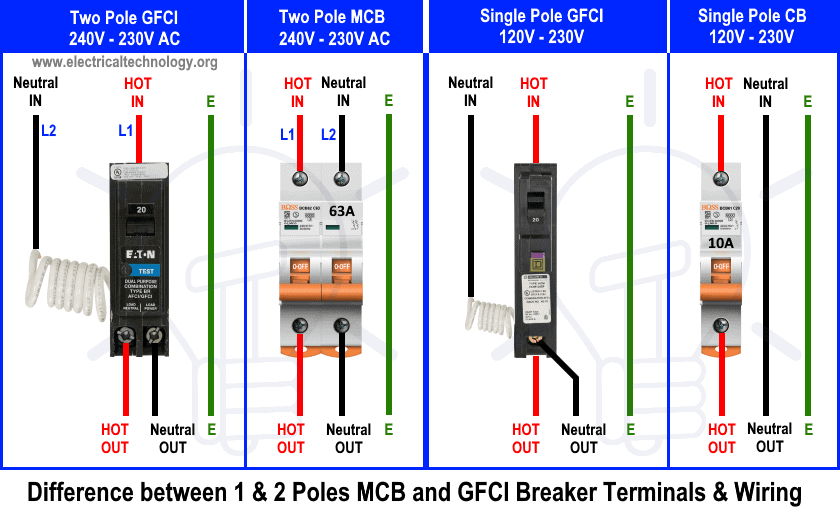
It is important to understand that the key difference between standard single-pole or two-pole circuit breakers and a GFCI breaker is the built-in white pigtail wire on the backside of the GFCI breaker. This pigtail must be connected to the neutral busbar in the main panel; otherwise, the GFCI will not operate correctly and will fail to provide proper protection. While there is a built-in white pigtail in the AFCI breaker, you may refer to the previous post for a detailed comparison between GFCI and AFCI breakers.
The following fig shows differences and terminal wiring of 1-pole and 2-pole standard breakers and GFCI breakers.
Related Post: How to wire a GFCI Outlet? – GFCI Wiring Circuit Diagrams
Requirement of GFCI in NEC
The current codes have been updated with new requirements for GFCI protection in the National Electrical Code (NEC) for 250V outlets and receptacles in specific locations in dwelling units.
According to 210.8(A), for Dwelling Units, all 120-240V outlets installed in the locations specified in 210.8(A)(1) through (A)(11) and supplied by single-phase branch circuits rated 150V or less to ground shall have ground-fault circuit-interrupter (GFCI) protection for personnel:
- Outdoors applications except receptacles supplied by a branch circuit that are not readily accessible in accordance with 426.28 or 427.22 (if applicable)
- Indoor damp and wet locations
- Bathrooms
- Boathouses
- Bathtubs or shower stalls
- Laundry areas
- Garages
- Crawl spaces
- Kitchens
- Sinks
- Basements except receptacles supplying only a permanently installed fire alarm or burglar alarm system
Non-Dwelling Units:
- Commercial Kitchens
- Bathrooms:.
- Rooftops
- Outdoor Areas
- Sinks
Specific Locations and Equipment:
- Boathouses
- Receptacles in Damp or Wet Locations.
- Hydromassage Bathtubs
- Electric Drinking Fountains:
Now that you have an idea, we will show different wiring circuit diagrams for single-pole, two-pole, three-pole, and four-pole (both single-phase and three-phase) GFCI circuit breakers.
box type=”info” align=”” class=”” width=””]
- The NEC – 210.8(A)(1) through (A)(11) for dwelling and non-dwelling unites mandates GFCI protection for circuits in bathrooms, garages, kitchens, laundry areas, crawl spaces, unfinished basements, and outdoor areas, as well as for certain appliances like dishwashers or sump pumps. A GFCI breaker ensures compliance for the entire circuit in these areas.
- GFCI protection is required for various applications in compliance with the following NEC Articles: 210.8, 406.3, 424.44, 426.28, 427.22, 511.12, 517.17, 517.20, 525.23, 530.44, 547.28, 555.35, 620.6, 625.54, 680.5, 680.21, 680.22, 680.23, 680.27, 680.32, 680.43, 680.44, 680.51 through 680.59, 680.62, and 680.71.[/box]
Wiring Single Pole GFCI Breakers
Wiring 15A – 120V GFCI Breaker
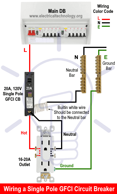
The following wiring diagram shows a 15A, 120V ordinary outlet wired and protected by a single-phase 15A, 120V, single-pole GFCI circuit breaker.
As shown in the figure, the built-in white wire in the GFCI should be directly connected to the neutral bar in the main panel board.
The Line (Hot, Live, or Phase) is connected directly to the GFCI input, and the output is connected to the line terminal of the ordinary outlet/receptacle. The silver screw labeled “N” on the GFCI is connected to the silver screw on the outlet via the output neutral wire from the GFCI to the outlet. The ground terminal (green screw labeled “G”) of the outlet is connected to the ground bar in the main distribution board.
This way, the 15A, 120V outlet is GFCI protected by the 15A GFCI breaker. You may use #14 AWG wire between the outlet and the GFCI. According to the 80% load rule in the NEC, no more than a 12A load should be connected to this 15A GFCI-protected outlet.
15A × 80% = 12A
You may safely connect up to 1440 watts load appliances to the 14A, 120V GFCI protected outlet.
Click image or open in a new tab to enlarge
Wiring 20A – 120V GFCI Breaker
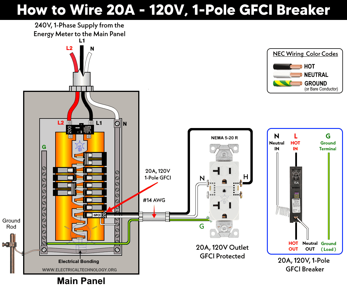
The same wiring configuration can be applied to a 20A, 120V circuit by using the correct wire size, an appropriately rated circuit breaker, and properly rated switches and outlets. As shown in the figure below, this includes wiring a 2-pole, 20A–120V GFCI breaker with a 20A–120V outlet (NEMA 5-20R).
Click image or open in a new tab to enlarge
Wiring 30A – 120V GFCI Breaker
Similarly, the following wiring diagrams shows a TT-30 (Travel Trailer) receptacle is protected by using 1-P, 30A – 120V GFCI breaker.

Wiring 2-Pole GFCIs without Neutral
Wiring 15A – 240V GFCI Breaker
Wiring 20A – 240V GFCI Breaker
The following wiring diagrams demonstrates a 2-Pole, 20A – 240V GFCI breaker is used to protect the 20A/250V (NEMA 6-20R) outlet.
Click image or open in a new tab to enlarge

Wiring 30A – 240V GFCI Breaker

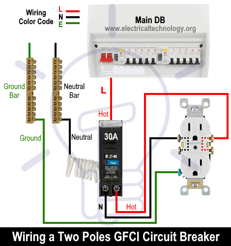
Wiring 50A – 240V GFCI Breaker
Wiring Two-Pole GFCIs with Neutral
As we know, in a 240V system, the neutral connection is typically not required. However, in certain cases, appliances must be connected to the neutral in accordance with the manufacturer’s specifications and user manuals.
The following wiring diagrams shows the different ratings of 2-pole GFCI breakers with neutral wire used in 3-P, 4-W configurations.
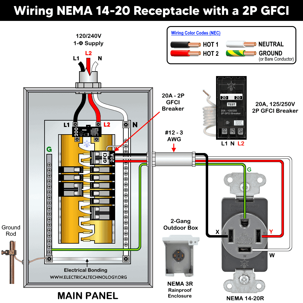
Wiring 20A – 120/240V GFCI Breaker
The following wiring diagram shows the installation of a 20A, 120/240V 2-Pole GFCI breaker with a 20A , 125/240V (NEMA 14-20) which required neutral connection.
Wiring 30A – 120/240V GFCI Breaker
In a two-pole, 3-wires configuration, the following 30A-125//250V (NEMA 14-30) grounding receptacle is wired and protected using 30A – 120/240V GFCI breaker.

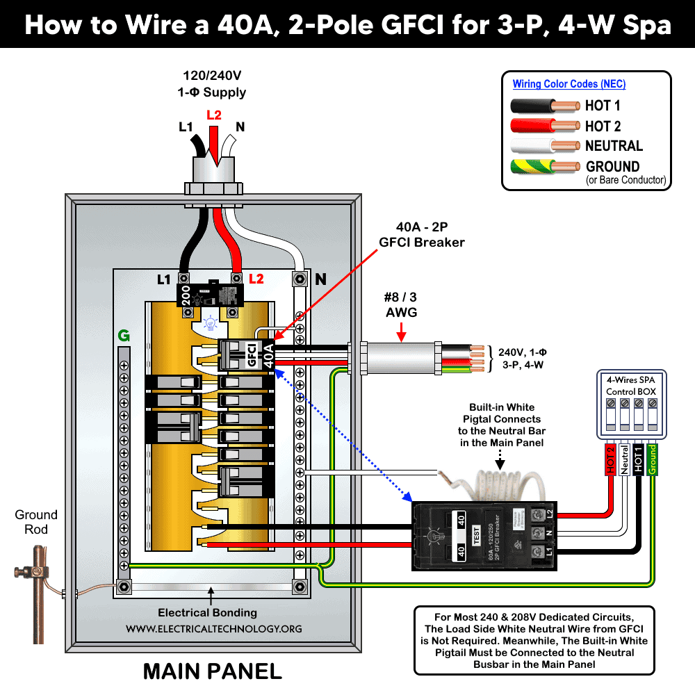
Wiring 40A & 50A – 120/240V GFCI Breaker for Spa & Hot Tub
The following wiring diagram shows a hot water tub spa or whirlpool spa wired and protected through a 2-pole GFCI circuit breaker using a three-wire system (two hot wires, one neutral, and one ground).
In this 4-wire GFCI wiring diagram, the built-in white wire from the GFCI is connected to the neutral busbar in the main panel. Two lines from the main panel (L1 and L2, single-phase 240V) are connected to the input terminals of the GFCI, which is installed in the L1 and L2 terminal slots in the panel or load center.
As shown in the figure, the three output terminals are connected to the spa control box according to the printed markings: the middle terminal is neutral, and the first and last terminals are the two lines (L1 and L2). Finally, the ground wire from the ground busbar is connected to the ground terminal in the spa control box.
Click image or open in a new tab to enlarge
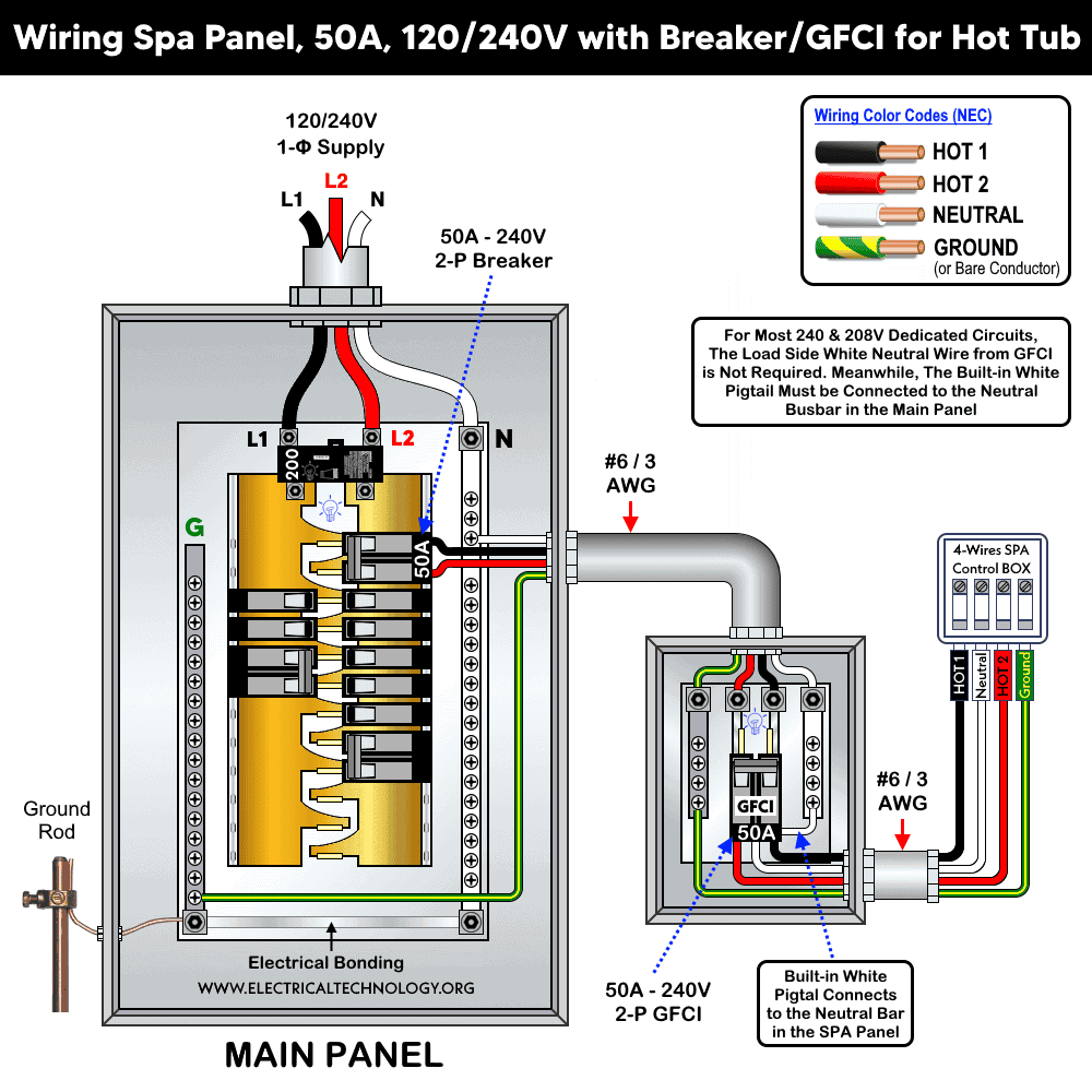
Similarly, the following wiring diagram shows a 50A – 120/240V spa panel box with a 2-pole GFCI breaker controlled by downstream 2-pole standard breaker in the main panel.
Click image or open in a new tab to enlarge
Wiring 50A – 120/240V GFCI Breaker
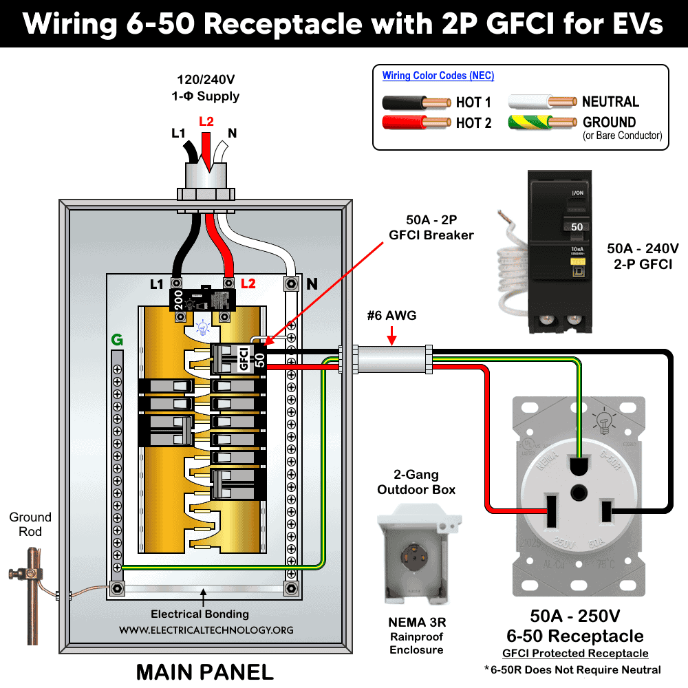
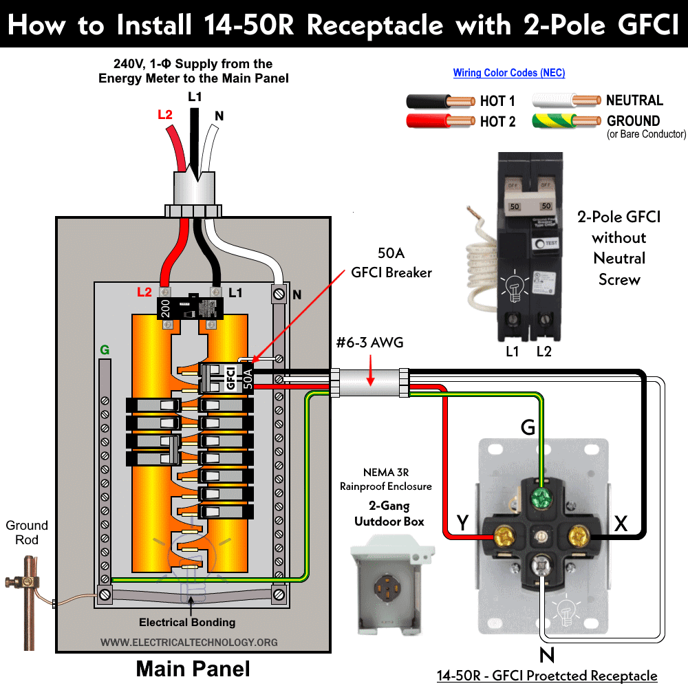
If the 2-pole GFCI breaker has only two output terminal screws (mostly used in 240V circuits), you will have to arrange a separate neutral from the neutral busbar in the main panel or load center. For example, the following wiring diagram shows a 2-pole GFCI breaker with two output terminals (L1 and L2) installed with a NEMA 14-50R outlet rated at 50A, 240V, which is used for heavy-duty EV charging, stoves, laundries, etc.
Click image or open in a new tab to enlarge
If the 2-pole GFCI breaker has three output terminal screws (mostly used in 120/240V circuits), you may directly wire the neutral to the center screw labeled “N”, and Line 1 and Line 2 to the first and last terminal screws, connecting to the outlet or any other load.
For example, the following wiring diagram shows a 2-pole GFCI breaker with three output terminals installed with a NEMA 14-50R receptacle rated at 50A, 240V, which is used for heavy-duty electric vehicle charging, mobile connectors, electric ranges, etc.
Click image or open in a new tab to enlarge

- A detailed Post on: How to Install NEMA 14-50R, 50 Amp Heavy Duty EV Outlets with GFCIs?
Wiring 60A – 120/240V GFCI Breaker
The following wiring diagrams shows a NEMA 14-60 receptacle/outlet is protected using 2-P, 60A – 240V GFCI breaker.

Wiring 3-Phase, 3-Pole GFCI Breakers
The following wiring diagram demonstrates how to wire a 20A, 120/208V, three-phase, three-pole GFCI breaker using a four-wire system (three hot wires, one neutral, and one ground).
As shown in the wiring diagram, the pigtail of the built-in white wire is connected to the neutral busbar in the load center. The three hot conductors (black, red, blue) are connected to the input terminals of the 3-phase GFCI.
Similarly, the output terminals are wired through the same phase wires from the GFCI to the three-phase load. If a neutral is needed, it should be connected from the neutral bar located in the main panel or load center.
Click image or open in a new tab to enlarge

It should be noted that this three-line wire supply arrangement will provide a 208V, three-phase supply to the load points. The same wiring diagram applies to a 120/208/240V (high leg delta), three-phase supply or any other three-phase power while wiring a 3-pole, 3-phase GFCI breaker.
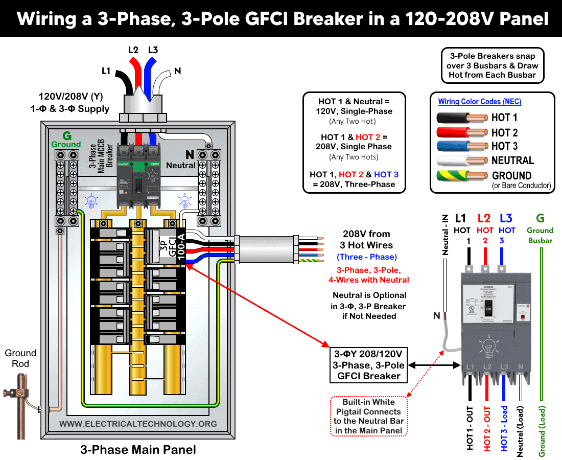
Similarly, the following wiring diagram illustrates a three-phase, three-pole, four-wire GFCI breaker installed in a 120/208V, three-phase panel. Note that the load neutral is optional and if the connected equipment does not require a neutral conductor, the neutral terminal on the three-phase GFCI breaker should remain unused.
Click image or open in a new tab to enlarge
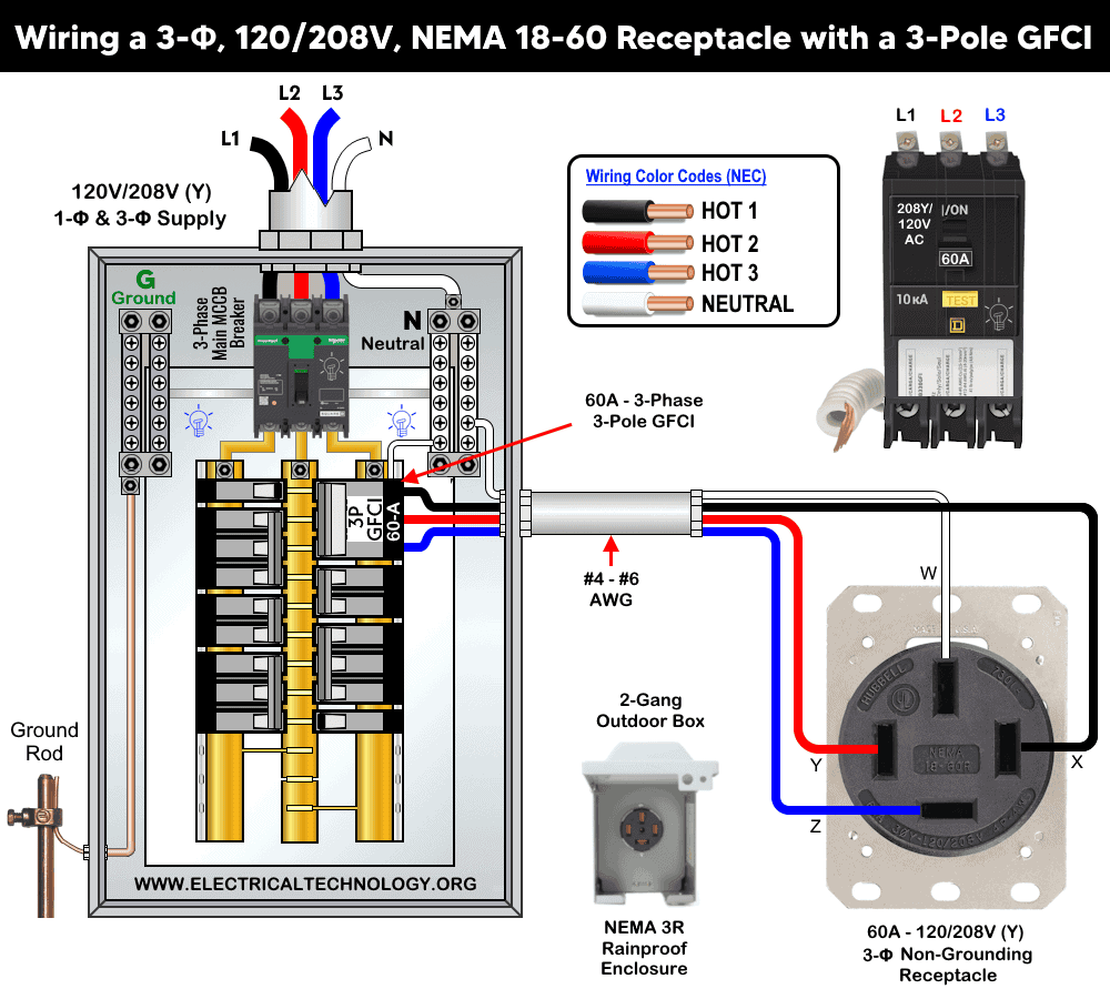
Moreover, the following wiring configuration is used to wire a 3-phase, 208Y/120V NEMA 18-60 receptacle. As illustrated below, the non-grounding receptacle is supplied via a 3-pole GFCI circuit breaker equipped with a neutral conductor and without EGC.
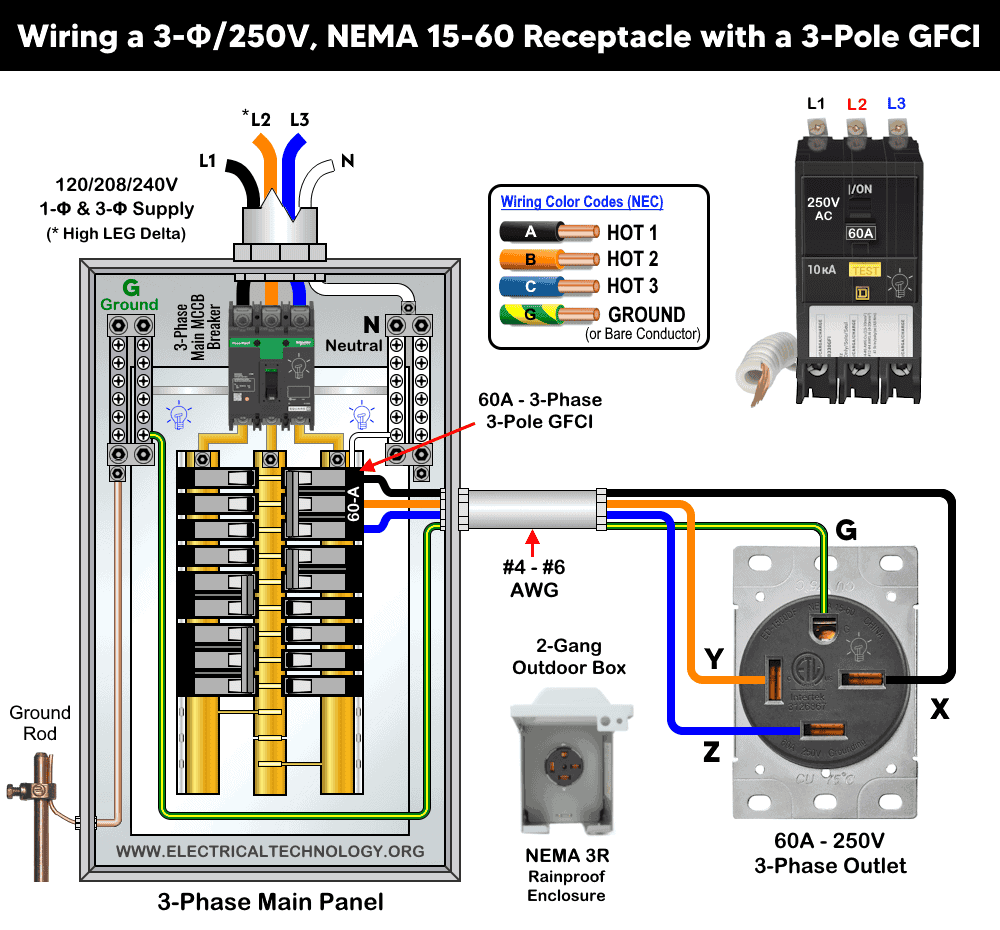
In addition, the diagram given below illustrates the wiring connection for a 3-phase, 120/208/240V, NEMA 15-60 receptacle. The circuit is protected by a 3-pole GFCI circuit breaker and, as shown, does not require a neutral conductor.
The wiring connections are same for both GFCI and AFCI breakers in both single phase and three phase circuits.
Related Posts:
Wiring a 3-Phase, 4-Pole GFCI Breaker (RCD/RCBO)
Since there are no official 4-pole GFCI products available, you may use a 4-pole RCCB or RCBO for the same purpose when needed. Although it’s unclear what specific scenario in North America would require a 4-pole GFCI, as a 3-pole GFCI with an additional neutral from the neutral bar can often suffice, this solution addresses a query from a member who needs all four wires secured in a single unit.
If you encounter a situation where you need to install and wire a 4-pole GFCI in a three-phase circuit, a quick fix is to wire a 4-pole RCCB, which functions similarly to a GFCI.
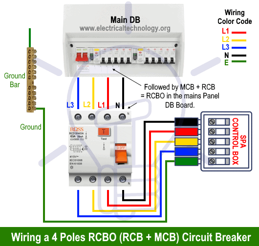
In the three-phase wiring diagram for GFCI, RCD, or RCBO, the three lines (L1, L2, and L3) and neutral are connected as inputs to the RCCB from the main board, following an MCB for overcurrent protection.
The lower four terminals and ground wire of the RCBO are connected to the spa control box in the following sequence: Red (L1), Yellow (L2), Blue (L3), Black (Neutral), and Green/Yellow (Ground/Earth).
The following diagrams show the three-phase four-pole RCBO (RCCB + MCB) circuit breaker used to control and protect a hot water spa.
For three-phase spa wiring, use 12 or 10 gauge wire for each line. For example, use #12 or 4.0mm² wire for up to 12kW, three-phase 415V – 480V systems where the maximum current is 18.2A. Use #8 or 6.0mm² wire for the same 12kW spa in a three-phase 208V system where the maximum current is 33.3A. For higher wattage, use the appropriate wire size according to the table and user manual.
Related Posts:
- Wiring of the Distribution Board with RCD (Residual Current Devices)
- How to Wire an RCBO? Residual Current Breaker with Overcurrent
Resources
Related Wiring Installation Diagrams and Tutorials:
- National Electrical Code (NEC) Requirements for Panelboards
- How Do GFCI and Standard Breakers Respond to Ground Faults?
- Why Doesn’t a Standard Breaker Protract Against Ground Faults?
- How Does a Standard Breaker Respond to Electrical Fault?
- Why Do We Need a GFCI & How Does it Protect During Faults?
- Why are Neutral and Ground Wires Separated in a Subpanel?
- Why Must Neutral and Ground Wires Be Bonded in the Main Panel?
- What Happens if the Neutral is Lost in the Main or Subpanel?
- Single Phase Electrical Wiring Installation in Home – NEC & IEC
- Three Phase Electrical Wiring Installation in Home – NEC & IEC
- How to Wire 120V & 240V Main Panel? Breaker Box Installation
- How to Wire a Subpanel? Main Lug Installation for 120V/240V
- How to Size a Load Center, Panelboards and Distribution Board?
- How to Determine the Number of Circuit Breakers in a Panel Board?
- How to Determine the Right Size Capacity of a Subpanel?
- How to Wire 120V Simultaneous Water Heater Thermostat?
- How to Wire 240V Water Heater Thermostat – Non-Continuous?
- How to Wire 3-Phase Simultaneous Water Heater Thermostat?
- How to Wire and Install an Electrical Outlet Receptacle?


I wants to know about types of earthing,,energy saving lights,safty divice,transformer safty and new incoming of electrical technology
Ac
Retired inside wiremen
Why is a plug intended for 15 amps shown attached to a 30 amp breaker?
I admit to doing something similar in mexico using a 240 volt 30 amp 2 pole breaker on a 15 amp circuit, only because it was available, but I wired in a 15 amp sub panel breaker so pump and wire was protected for amp overload while people were protected for current to ground.
I Should have said 30 amp 240 volt GFCI in comment.
4pole D.C moter
I will follow you for more information electrical wiring diagrams.
Notice: if you are not an electrician, leave this work to the professionals. The only way to make sure you and your family is safe is to have a valid licensed electrician perform these tasks. Thanks.
You got that right.
Knowledgeable and helpful
Do you have telegram subscription channel so I can get much of these