How to Wire 120/240V Main Panel – Breaker Box Installation
Wiring Installation of Single Phase 120V & 240V Circuits & Breakers in Main Service Panel
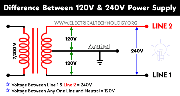
In the USA and Canada (following NEC and CEC), distribution transformers typically receive 4.5 kV to 7.2 kV on the primary side and step it down to 120V single-phase and 120/240V split-phase for residential applications. The primary side of the distribution transformer is supplied by two conductors known as a high-voltage line and a neutral respectively.
The secondary winding of the transformer is center-tapped, producing three output conductors: Hot 1 (Line 1), Hot 2 (Line 2), and Neutral. The voltage between either hot conductor (Hot 1 or Hot 2) and the neutral is 120V, while the voltage between the two hot conductors is 240V. Both are single-phase supplies, but the two hot conductors are 180° out of phase with each other, which is why the voltage between them is 240V instead of 120V.
These three wires enter the meter box and then connect to the main panel. In the following tutorial, we will show how to wire 120V single-phase and 240V split-phase circuit breakers and loads inside a residential main panel.
Inside Main Breaker Box
The figure below shows a typical breaker panel used for 120V and 240V circuits. Three conductors enter the main panel from the energy meter and main disconnect as:
- Hot 1 (Line 1) = Black Color
- Hot 2 (Line 2) = Red Color (used for illustration only)
- Neutral = White Color
Click image or open in a new tab to enlarge
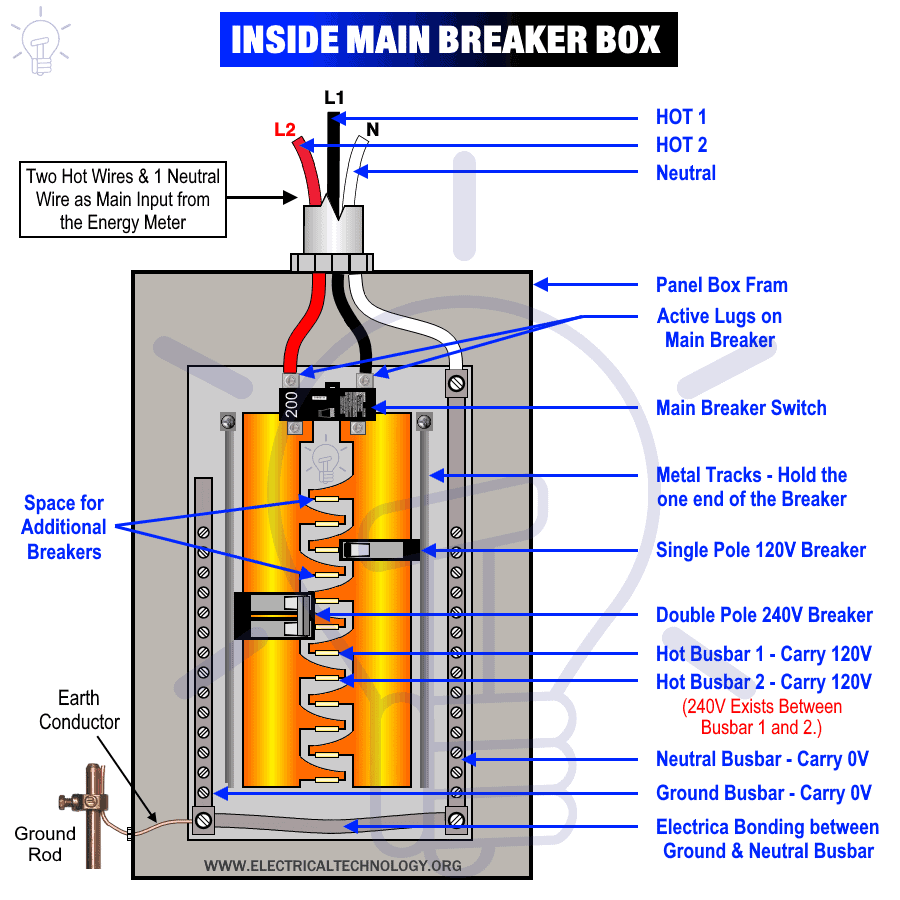
Hot 1 and Hot 2 are securely connected to the lugs of the main circuit breaker (main switch). Keep in mind that these lugs remain energized at all times, even when the main breaker is switched OFF.
The main breaker feeds the two hot busbars inside the panel. For illustration, they are shown in black and red. Each busbar carries 120V, and the voltage between the two busbars (Hot 1 and Hot 2) is 240V.
The white neutral conductor is connected to the neutral busbar, which carries 0V. The neutral busbar is bonded to the grounding busbar for safety, and this grounding bar also carries 0V. All metal enclosures must be properly grounded according to NEC requirements.
In this configuration:
- Voltage between Hot 1 and Neutral: 120V (single phase)
- Voltage between Hot 2 and Neutral: 120V (single phase)
- Voltage between Hot 1 and Hot 2: 240V (split phase)
- Voltage between Neutral and Ground: 0V
For 120V single-phase circuits, a single-pole breaker connects one hot busbar (either Hot 1 or Hot 2) to the neutral. For 240 V split-phase circuits, a two-pole breaker connects to both hot busbars (Hot 1 and Hot 2).
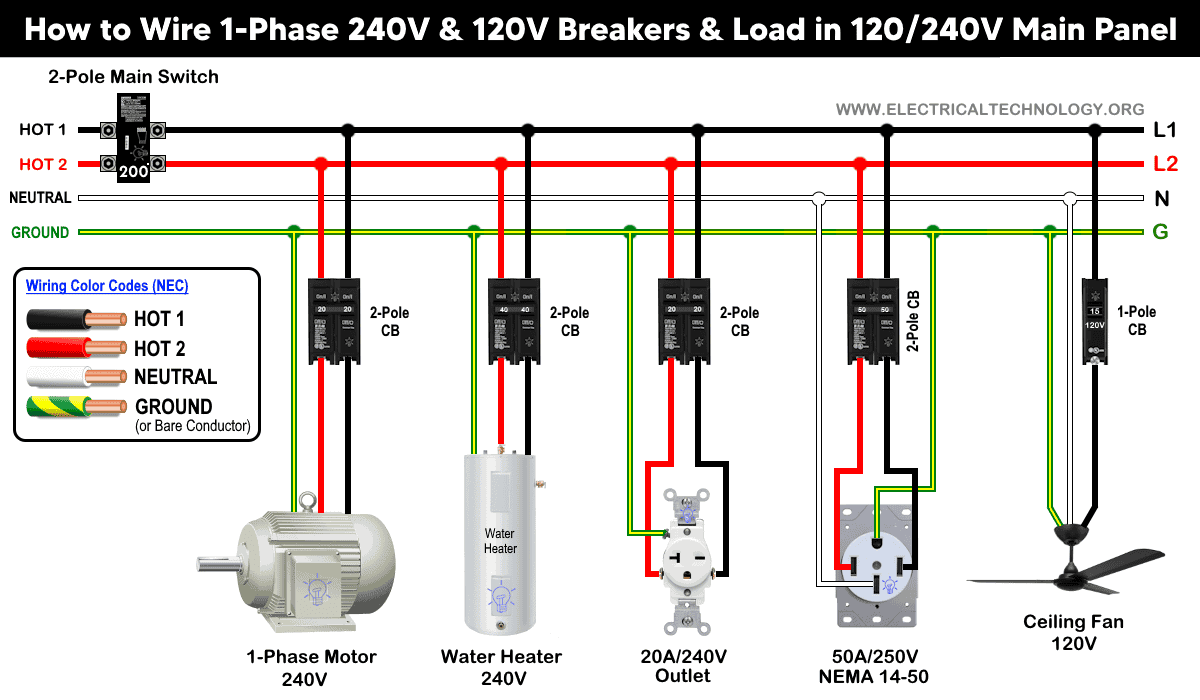
The figure below illustrates a typical main service panel showing 120V and 240V single-phase/split-phase wiring and breaker installation.
Click image or open in a new tab to enlarge

How to Wire 120V Circuits & Breakers
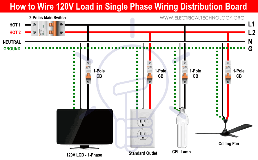
The following tutorial explains how to wire a 120V single-phase breaker and load points in a residential panel.
120V single-phase circuits are commonly used in homes for lighting and receptacle outlets. To install such a circuit, mount and connect a single-pole 15A or 20A breaker to either one of the hot busbars (Hot 1 or Hot 2) using the metal mounting tracks that hold the circuit breakers in place.
For example, if a single-pole breaker is mounted on Hot 1, the breaker’s output terminal (black wire) is connected to the ceiling fan. The neutral wire (white) from the fan is connected to the neutral busbar. The bare copper or green/yellow grounding conductor is connected to the fan’s grounding terminal. For ON/OFF control of the fan, a single-pole wall switch must be installed only on the hot (live) conductor, never on the neutral.
Use #14 AWG for 15A breaker and load, and use #12 AWG wire for a 20-amp load and breakers (Per As per NEC Table 310.16, Table 210.24(1), and NEC 240.4(D)(6)). A 20A receptacle is permitted only on a 20A breaker; do not install a 20A receptacle on a 15A breaker.
As per NEC 210.19(A)(1) and NEC 210.20(A), a 20A breaker is recommended for circuits with up to 16A of (continuous – which last 3 or more hours) load because circuit breakers must be sized at 125% of the continuous load.
In simple terms, a breaker should carry no more than 80% of its rated current. For example, a 12A continuous load should be installed on a 15A breaker. Similarly, a 20A breaker should be used for 16A continuous and max 20A non-continuous load points.
Some example NEMA receptacles used in 120V configuration are as follow:
- NEMA 5-15, 5-20, 5-30, 5-50 as well as locking receptacle i.e. L5-15, L5-20, L5-30, L5-50
- NEMA TT-30
- NEMA 1-15 – non-grounding (obsolete for new installations).
Click image or open in a new tab to enlarge
 How to Wire 240V Circuits & Breakers
The following tutorial explains how to wire split-phase (240V single-phase) circuit breakers and load points in a residential distribution panel.
Split-phase or 240V single-phase circuits are typically dedicated circuits, meaning they are intended for individual high-power appliances such as dryers, stoves, washing machines, air conditioners, water pumps, and motors.
To install a 240V circuit, mount a two-pole breaker onto the panel’s metal mounting tracks, which secure the breaker onto both hot busbars. The rating of breaker should be sized properly as per circuit requirement . The two output conductors from the breaker connect directly to the load. A bare or green grounding conductor must also be connected to the load’s grounding terminal. The size of Equipment Grounding Conductor (EGC) can be found using NEC 250.122 and Table 250.122.
In standard 240V split-phase circuits, a neutral conductor is not required in 2-pole, 3-wire receptacles (such as NEMA 6-15, 6-20, 6-30, 6-50, unless the appliance specifically needs it. Some modern appliances require both 240V (hot-to-hot) and 120V (hot-to-neutral) such as NEMA 14 series e.g. NEMA 14-20, NEMA 14-30, NEMA 14-50, 14-60 etc. for EV charging. If unsure, always check the appliance’s user manual or consult the manufacturer.
Some other NEMA receptacles used in 240V configuration are as follow:
- NEMA 10-20, 10-30, 10-50 as well as locking receptacle i.e. L10-20, L10-30, L10-50. They are non-grounding and prohibited in new installations. Same is the case with NEMA 2-20 non-grounding receptacle.
Never use mismatch rated breakers such as a 30A breaker for 15A, 20A, or 40A outlets or loads. The same 125% rule applies to 240V circuits: the continuous load must not exceed 80% of the breaker rating. For example, a 30A breaker (single-pole or two-pole) may supply up to a 24A continuous load.
As per NEC Table 310.10, the following wire size (copper recommended) should be used with the single-pole or two-pole breakers and loads points.
- 15A Circuit = Use 14 AWG
- 20A Circuit = Use 12 AWG
- 30A Circuit = Use 10 AWG
- 40A Circuit = Use 8 AWG
- 50A Circuit = Use 6 AWG
- 60A Circuit = Use 6 AWG
- 70A Circuit = Use 4 AWG
- 80A Circuit = Use 3 AWG
- 90A Circuit = Use 2 AWG
- 100A Circuit = Use 1 AWG
- 125A Circuit = Use 1/0 AWG
It is also against code to use two separate single-pole breakers to supply a 208V or 240V circuit. If two single-pole breakers must be used, they must have:
- A common trip or handle tie (both switch ON/OFF together)
- The same amperage rating
- Installation on opposite busbars (Hot 1 and Hot 2)
- If installed on the same busbar, the appliance will receive the wrong voltage (120V instead of 240V).
Good to know: Four conductors (Hot 1 + Hot 2 + Neutral + Ground) are required for grounded 125/250V single-phase circuits, plugs and outlets, such as NEMA L14-30R, L14-20R, 14-60R, 14-50R, 14-30R, 14-20R, and 14-15R receptacles.
Click image or open in a new tab to enlarge
Wiring Color Codes:
We have used the NEC + general practice wiring color codes in this tutorial as follows. Please follow the National Electric Codes and associated practiced wiring color codes or other applicable color codes related to general practice or specific area.
- Black = Hot 1 or Line 1
- Red = Hot 2 or Line 2
- White = Neutral Wire
- Green or Bare Copper = Ground as EGC
For 240V systems, the recommended hot conductor colors are Black and Red, or both conductors may be Black. If a white wire is repurposed as a hot conductor in a 240V circuit, it must be re-identified with black tape or a black marker at both ends so it is clearly recognized as a hot wire and not as a neutral.
Do not use green, green/yellow, or bare conductors for any wire that carries voltage. Use copper wire only in the main panel to minimize resistance and heat; aluminum conductors should not be used in these connections.
Safety Precautions
- Disconnect the power source (and verify it is truly OFF) before servicing, repairing, or installing electrical equipment. Turn OFF the main breaker in the main panel.
- Never touch the screws above the main breaker. These terminal screws are always live, regardless of whether the breaker is ON or OFF.
- Never touch wet surfaces or metallic parts while working on energized circuits.
- Carefully read and strictly follow all safety instructions related to this tutorial or any electrical work.
- Always use the correct wire gauge size, appropriate outlet and switch ratings, and the proper size of circuit breakers. You may also use a wire & cable size calculator to determine the correct gauge.
- Never attempt electrical installation or repair without proper knowledge of electricity and supervision. Work should always be done under the guidance of an experienced and qualified person.
- Performing electrical work yourself can be dangerous and may also be illegal in some areas. Consult a licensed electrician or your local power utility before making changes to any wiring system.
- The author is not responsible for any loss, injury, or damage caused by the improper use of this information or incorrect wiring practices. Electricity is extremely dangerous. Stay safe and exercise maximum caution at all times.
Resources:
Related Main Panels Wiring Tutorials
- How to Wire 120/240V Main Panel – Breaker Box Installation … You are Here
- How to Wire 120V/208V, 1-Phase & 3-Phase Main Panel?
- How to Wire 120/208/240V High Leg Delta 1-Phase & 3-Phase Main Panel?
- How to Wire 277/480V, 1-Phase & 3-Phase Main Service Panel?
- How to Wire 347/600V, 1 and 3-Phase Main Service Panel?
- How to Wire a Subpanel? Main Lug Installation for 120V/240V
- How to Wire Spa Panel for Hot Tub using 2-P GFCI & Breaker
- Single Phase Electrical Wiring Installation in Home according to NEC & IEC
- Three Phase Electrical Wiring Installation in Home – NEC & IEC
- How To Wire a Single Phase kWh Meter – 120V/240V
- How to Wire a Three-Phase Meter? 120/208/240/277/347/480/600V
Sizing Breakers, Wires, and Panels
- How to Size a Load Center, Panelboards and Distribution Board?
- How to Determine the Right Size Capacity of a Subpanel?
- How to Find the Right Wire Size for 100A Service 120V/240V Panel?
- How to Size a Circuit Breaker?
- How to Find the Proper Size of Wire & Cable In Metric & Imperial Systems
- How to Size a Breaker and Wires in AWG with EGC for Load?
- How to Size Service-Entrance Conductors and Feeder Cables?
- How to Size Feeder Conductors with Overcurrent Protection
- How to Size a Branch Circuit Conductors with Protection?
- How to Size Equipment Grounding Conductor (EGC)?
- How to Size Grounding Electrode Conductor (GEC)?
- How to Size Motors FLC, HP, Voltage, Breaker Size and Wire Size
- What is the Correct Wire Size for 100A Breaker and Load?
- What is the Right Wire Size for 15A Breaker and Outlet?
- What is the Suitable Wire Size for 20A Breaker and Outlet?
Standard Breakers & GFCI Breakers Wiring Installations
- How to Wire a 1-Pole Breaker
- How to Wire a 2-Pole Breaker
- How to Wire a 3-Pole Breaker
- How to Wire a 1-Pole GFCI
- How to Wire a 2-Pole GFCI
- How to Wire a 3-Phase, 3-Pole GFCI
- How to Wire a Tandem Breaker
- How to Wire GFCI Circuit Breakers
- How to Wire an AFCI Breaker
General Outlets and GFCI/AFCI Receptacles Wiring
- How to Wire an Outlet Receptacle? Socket Outlet Wiring Diagrams
- How to wire a GFCI Outlet?
- How to Wire GFCI Combo Switch and Outlet
- How to Wire an AFCI Combo Switch
- How to Wire an AFCI Outlet?
- How to a Wire 3-Way Combination Switch and Grounded Outlet?
- How to Wire Combo Switch and Outlet? – Switch/Outlet Combo Wiring Diagrams
- How to Wire a 15A – 125V Outlet – NEMA 5-15 Receptacle
- How to Wire a 20A – 125V Outlet – NEMA 5-20 Receptacle
- How to Wire a 15A – 250V Outlet – NEMA 6-15 Receptacle
- How to Wire a 20A – 250V Outlet – NEMA 6-20 Receptacle
- How to Wire a 50A – 125/250V Outlet – NEMA 14-50 Receptacle
Switches Wiring
- How to Wire Single Pole, Single Throw (SPST) as 2-Way Switch?
- How to Wire Single Pole, Double Throw (SPDT) as 3-Way Switch?
- How to Wire Double Pole, Single Throw Switch? Wiring DPST
- How to Wire Double Pole, Double Throw Switch? Wiring DPDT
- How to Wire Double Switch? 2-Gang, 1-Way Switch – IEC & NEC
- How to Wire 4-Way Switch (NEC) or Intermediate Switch as 3-Way (IEC)?
- How to Wire Auto & Manual Changeover & Transfer Switch – (1 & 3 Phase)
Finding the Number of Breakers/Outlets in a Circuit
- How to Determine the Number of Circuit Breakers in a Panelboard?
- How to Find the Number of Outlets on a Single Circuit Breaker?
- How to Find Voltage & Ampere Rating of Switch, Plug, Outlet & Receptacle
- How to Calculate the Number of Fluorescent Lamps in a Final Sub Circuit?
- How to Calculate the Number of Incandescent Lamps in a Final Sub Circuit?
- How to Determine the Number of Lighting Branch Circuits?
- How to Determine the Number of Branch Circuits? – 3 Ways
- How to Find the Number of Lights on a Single Circuit Breaker?
General Wiring Installation Tutorials:
- How to Toggle Electric Water Heater Between 120V and 240V?
- How to Wire 120V Water Heater Thermostat – Non-Simultaneous?
- How to Wire 240V Water Heater Thermostat – Non-Continuous?
- How to Wire 3-Phase Simultaneous Water Heater Thermostat?
- How to Wire Twin Timer for 120V/240V Circuits – ON/OFF Delay
- How to Wire ST01 Timer with Relay & Contactor for 120V/240V Motors?
- How to Wire Multifunction ON/OFF Delay Timer for 120V/240V Motors?
- Even More Residential Wiring Installation Tutorials


Now I know the the main trick between 120V and 240V panel circuits wiring. Thanks for that.
Hello there, Your site looks fantastic as a resource. I am an Australian electrician who would like to use your site as a resource but am not sure if ‘when relevant ‘ relates to the S.A.A (Australian Standard). ie. I am about to look into your ‘Distribution Board/Meter Panel’ wiring configuration template but is it according to our Codes? Kind Regards Jason Burns
Thank you for appreciation. As these resources clearly shows the article drawings and wiring codes are only related to IEC and NEC. There is still lit bit difference between IEC and S.A.A (Australian Standards) and if you compare, there will be little bit difference. So still you will have to check and match with the local area codes such as SAA. Thanks and regards
Does this stand true when wiring a sub panel? I’ve recently read that you cannot feed single pole breakers from a dual pole feed or main breaker. Reading your article is exactly what I’ve always followed and understood as being correct. I plan on installing a new sub panel which will be fed by 1 30a dual pole breaker, sub box will contain 2 15a and 1 20a single pole breakers for lighting and outlets. All wire and hardware requirements will be observed to fulfil 30a code requirements, do you see any issues with this installation?
Great Resource!
Ground and Neutral wires are mislabeled on the #10-3 wiring on the panel drawing.
Thank you for pointing this out. We have corrected it accordingly.
Outstanding work. Very helpful.