How to Wire a Subpanel? Main Lug Installation for 120V/240V
Wiring a Subpanel for 120V & 240V with GFCI – NEC – US
What is a Main Panel?
According to NEC (National Electric Code: Article 1 00-Definitions), a Main Panel (also known as Panelboard, load center, breaker box and distribution board etc.) is a cabinet or cutout box which contains on controlling and protective devices (such as circuit breakers, fuses, switches etc.) used to control and protect the light, heat, and power circuits. The panel board should be accessible only from the front and installed/mounted against the wall or other solid structures.
A main panel is the first line of defense against the electric surges and other faults (short circuit, overload, over current etc.) which protects electrical appliances and prevents electric shock and hazardous fire.
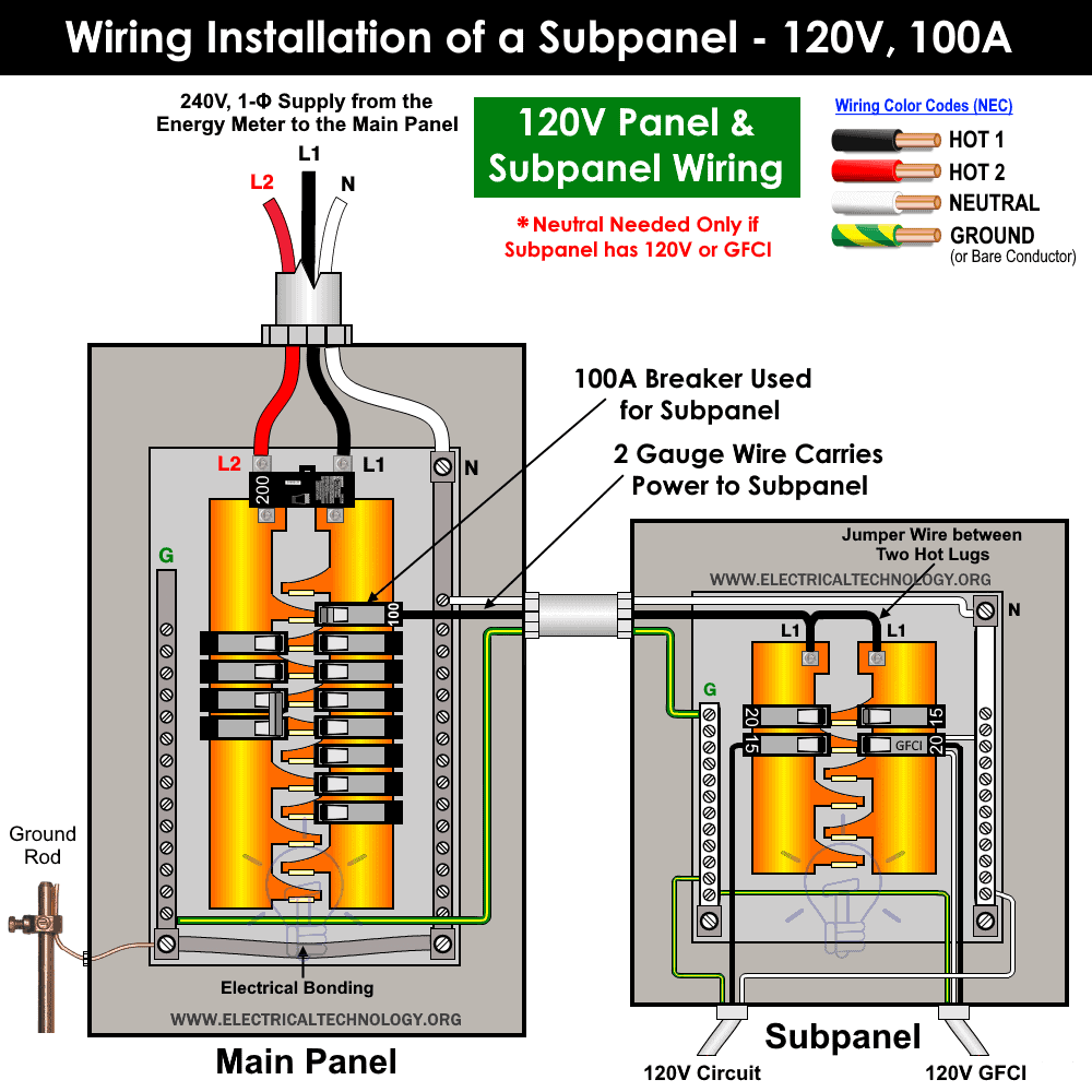
The main panel is directly connected to the feeder cables (from the energy meter and distribution transformer mounted on the utility pole). In residential applications, three wires (i.e. Black as Hot 1, Red as Hot 2 and White as Neutral) enters the main panel to provide 120V and 240V single phase supply voltage.
The two hot wires i.e. L1 and L2 are connected to the two poles main breaker, the Neutral is connected to the Neutral terminal in the panel box, and Ground wire is connected to the ground wire (Grounding/Earthing System). Keep in mind that the Neutral busbar terminal and Ground busbar terminal in the main panel is electrically bonded in single phase 240V & 120V electric power supply system.
Related Post:
- How to Size a Load Center, Panelboards and Distribution Board?
- How to Wire 120V & 240V Main Panel? Breaker Box Installation
- How to Wire 240V, 208V & 120V, 1 & 3-Phase, High Leg Delta Main Panel?
What is a Subpanel?
A subpanel (Remote Panel in NEC) is a smaller service panel derived from the main panel via two poles circuit breakers to securely distribute electric power to the other parts in the building, home, garage or any other specific applications in the premises.
A subpanel does the same job as the main panel i.e. it provides protection against surges, electric shock and other electric faults. The subpanel is fed-up by 2-Poles, 240V breaker at the main panel via two hot wires (L1 & L2), a Neutral wire “N” and Ground wire “G”.
Keep in mind that there is no need to bond Ground with Neutral in the subpanel (as they are already bonded in the main panel). In addition, Neutral in the subpanel is only needed when there are 120V circuits or GFCI circuit breakers/outlets. Moreover, two separate GFCI breakers should not be used for the same circuit to prevent the unwanted tripping conditions.
There are many types of main and sub panels by different manufacturers such as Eaton, Schneider, ABB, Siemens etc. for different applications such as Indoor & outdoor (weathertight).
In short, a Subpanel is used to provide:
- Additional circuit spaces for smooth operation
- Separate uses of electric power control to the circuits
- Protection and safety consideration with secure electric distribution system
Related Posts:
- How to Determine the Right Size Capacity of a Subpanel?
- How to Find the Right Wire Size for 100 Amp Subpanel in AWG?
Wiring Installation of a 60A Subpanel for 120V & 240V
The following wiring diagram shows the installation of a 60A subpanel for both 120V and 240V. You may use the current rating according to the system requirement i.e. 50A, 60A, 100A, 150A and so on. We have used 60A for illustration purposes only.
Click image to enlarge
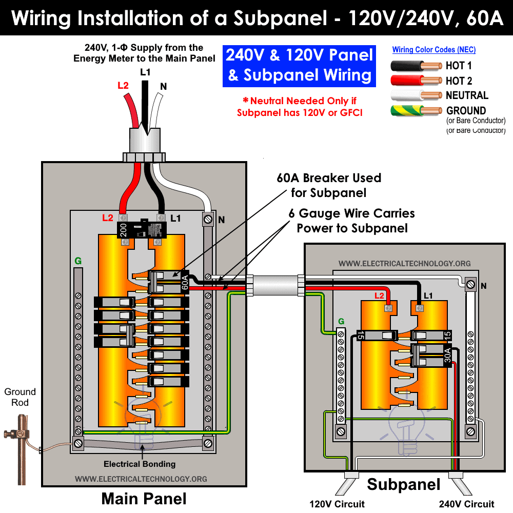
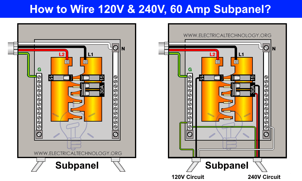
As shown, a two pole 60A breaker is fed-up via the main panel two hot busbars. The output wires as (L1 = Hot 1 (Black color) and L2 = Hot 2 (Red Color)) from the 2-poles breaker connected to the two busbars in the subpanel namely L1 and L2.
Similarly, the Neutral “N” and Ground “G” wires from the main panel enter to the subpanel and connect to the Neutral terminal and ground terminal respectively.
This sub-panel now can supply both 120V and 240V to the branch circuits via single pole and two poles (15A, 20A or 30A CBs).
Click image to enlarge
Keep in mind that if the distance between the main panel and subpanel is greater than 140feet, you may connect the ground to the nearest ground wire instead of laying a long cable to the subpanel. If so, you will have to increase the wire gauge size as well (e.g. from #6 gauge to #4 gauge and so on.
You may use #6 gauge wire for 60A circuit breaker from the main panel to the subpanel. Keep in mind that Neutral is only needed if there are GFCI circuit breakers, GFCI outlets or 120V single phase circuits.
- The main breaker lugs are always Hot no matter if the main switch is OFF or ON. They only can be switched off by pulling the energy meter or safety switch between main panel and energy meter.
- NEC does not allow the use of a 30A breaker for 20A outlets and switches etc. The links are given in the instruction NOTE (below this post) for sizing the breaker, wires, switches and outlets etc.
- a 240V, double pole breaker can only be used for a single appliance. Also, 2 Single pole breakers can’t be used for 240V appliances unless the ON/OFF button is bonded (i.e. a single switch should control the ON/OFF operation of both 1-Poles breakers)
Related Posts:
- How to Wire 208V & 120V, 1-Phase & 3-Phase Main Panel? Distribution Board Wiring
- How to Wire 277V & 480V, 1-Phase & 3-Phase, Commercial Main Service Panel?
Wiring Installation of a 150A Subpanel for Only 240V
The following wiring diagram shows the installation of a 150A subpanel for 240V only. We have used the typical 200A two poles circuit breaker in the main panel box while the the total ampacity of load circuits is 150A.
Click image to enlarge
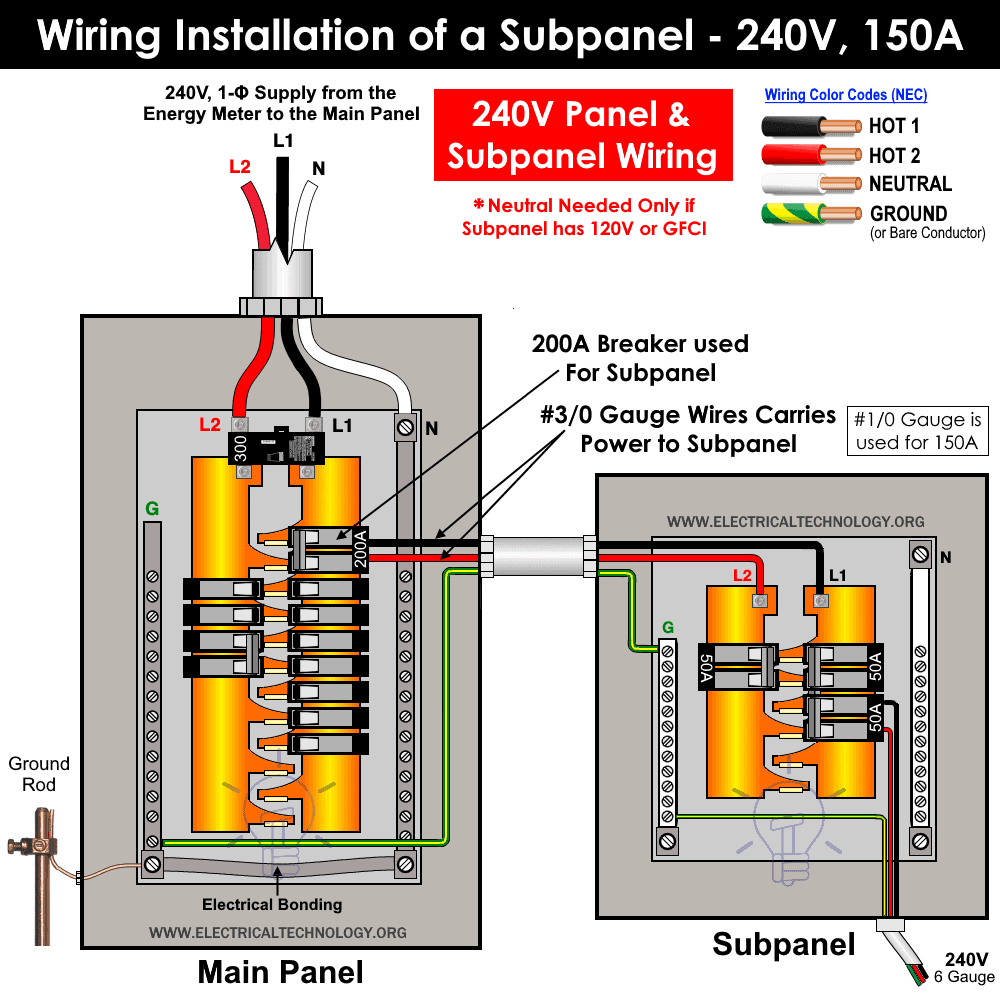
As shown, a total three wires enters from the main panel (2-Poles breaker) to the 240V subpanel via Hot1 “L1”, Hot2 “L2” and Ground “G”. You may notice that there is no neutral wire in the subpanel. It is because we run only 240V circuits where white neutral is no longer needed.
If we have to run single phase 120V circuits or 2-poles 240V GFCI breaker, we will connect the white neutral wire from the main service panel to the subpanel box.
Click image to enlarge
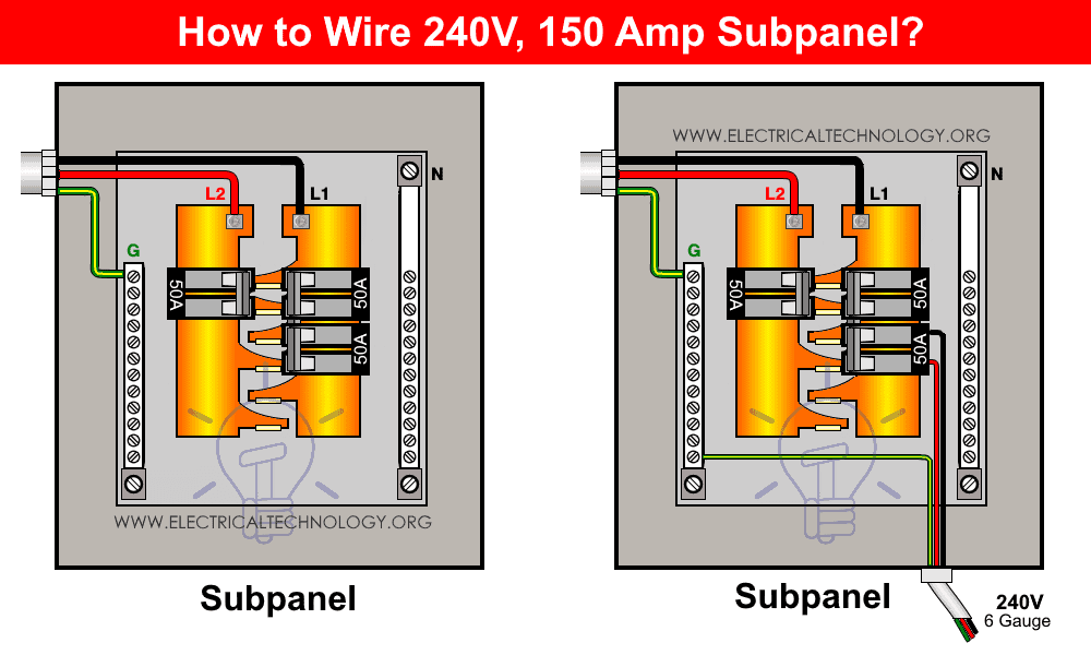
Keep in mind that #3/0 gauge wires should be used for 200A breaker and #1/0 gauge wire for 150A circuit breaker (NEC 2017 – Table 310.15(B)(16) & 310.15 (B)(7) “1-7”.
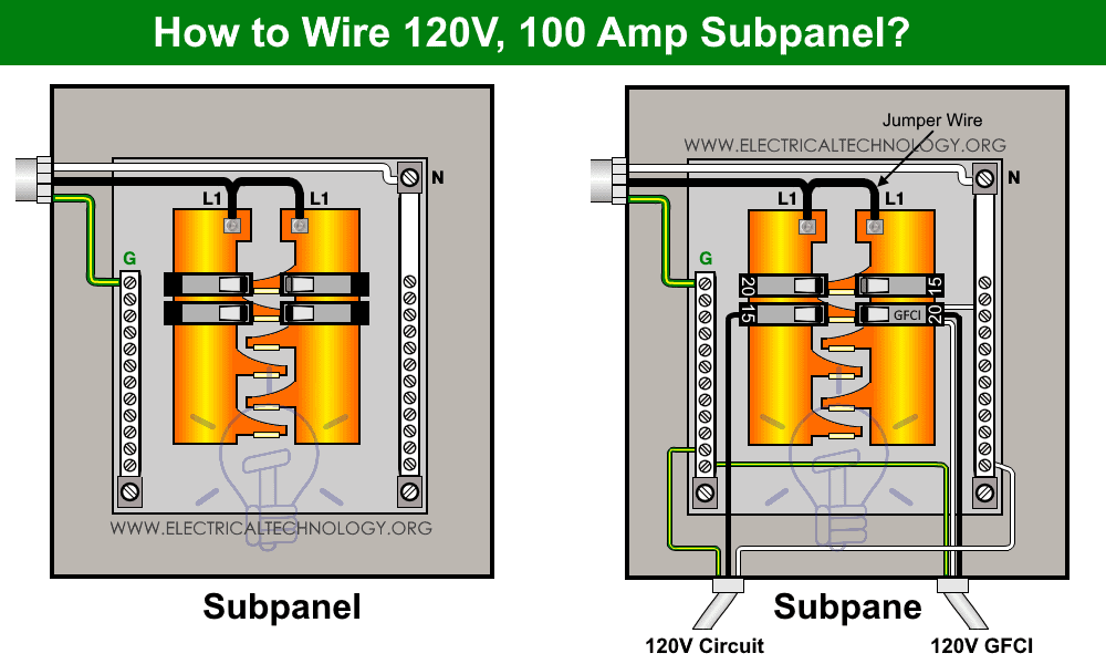
Related Posts: The following wiring diagram shows the installation of a 100A subpanel for 120V only. We have used 100A, single pole breaker in the main breaker box for illustration purposes only. You may use lower rating e.g. 60A, 50A, 40A or even 30A. Click image to enlarge As shown, we need all the three wires i.e. Hot 1 (as Line 1 from the 1-Pole Breaker), Neutral from the Neutral busbar and Ground from the ground terminal. To get only 120V supply voltage, you would have to connect the Hot 1 ( as line in the black color) to both hot lugs in the subpanel through jumper wire (see fig). This way, the single Hot wire is connected to both hot lugs which fed-up 120V load points. In the fig below, both miniature circuit breakers and GFCI circuit breaker are connected to to power up the load circuits via Hot, Neutral and Gerund wire. Click image to enlarge Related Posts:
We have used the NEC + general practice wiring color codes in this tutorial as follows. The recommended colors for hot wires in 240V systems are Black & Red or both as Black Colors. If a white wire has been used in 240V which carries voltage, it must be covered with a black strip or a tap wrapped around it. This way, it can be easily identified as hot wire which is used as hot wire, and not as a neutral wire. Do not use green, green with yellow stripe or a bare conductor for those wires which carry voltage. Only and only use copper wire to reduce the resistance and heat instead of aluminum wires in the main panel box wiring.
Related Posts: Related Posts: Related Wiring Installation Tutorials:
Wiring Installation of a 100A Subpanel for Only 120V
Wiring Color Codes:
Safety Precautions