How to Make a DIY Breadboard Wristwatch Using ATtiny84A Microcontroller?
A breadboard LED wristwatch is an innovative electronic gadget and DIY project for enthusiasts. The watch is based on an ATtiny84A microcontroller and a few electronic components, and it is designed to display the time in hours and minutes on a bubble 7-segment LED display. For a beautiful look, you may use a fancy case with dimensions of approximately 37x23x3.5mm.
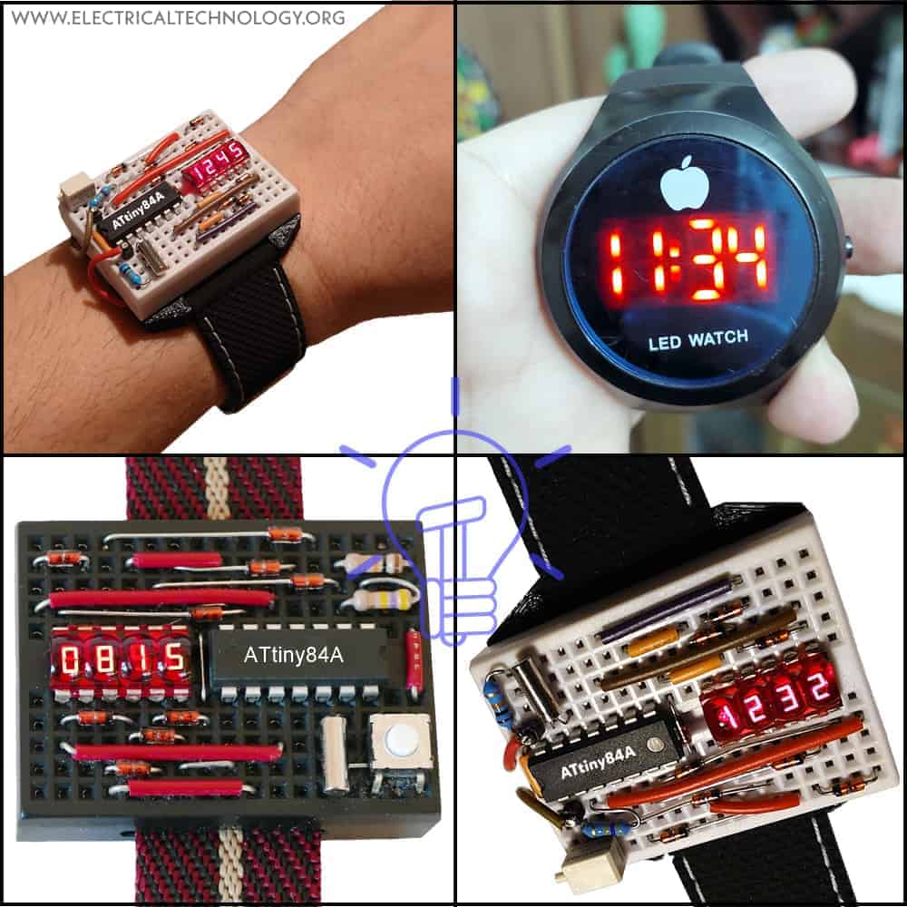
In this article, we will provide a comprehensive technical guide on how to build a breadboard LED wristwatch using an ATtiny84A microcontroller.
Components Required:
To build a breadboard LED wristwatch, you will need the following materials:
- ATtiny84A Microcontroller
- STNS01 IC – Integrated Li-Po Battery Charger
- Micro 7-Segment LED Display – QDSP-6064 Bubble Display
- 32.768kHz Crystal Oscillator – (Q-32.768000K-TC38-20-B-12,5)
- 9 Nos. of Schottky Diodes
- Two Resistors – 470kΩ & 10kΩ
- 3V.1 Li-Po Battery
- Breadboard
- Tact Push Button
- Jumper Wires
ATtiny84A Microcontroller:
The ATtiny84A microcontroller is the brain (MCU) of our breadboard LED wristwatch. It is an 8-bit microcontroller with 14 I/O pins, 8kB of flash memory, 512 bytes of SRAM, and 512 bytes of EEPROM. The ATtiny84A microcontroller is programmed using the Arduino IDE, which makes it easy to write, test, and upload code to the microcontroller.
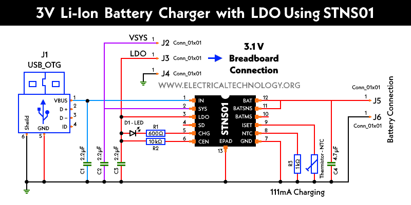
STNS01 IC – PSU Unit
The STNS01 IC is a programmable voltage reference and voltage monitor device (PSU – Power supply unit) with LDO (Low Dropout Regulator) manufactured by STMicroelectronics. It is a precision voltage reference with a low dropout voltage and an accurate output voltage that can be programmed through an I2C interface.
The STNS01 as 6-pin SOT23 package is designed to use use in space-constrained applications, including battery-powered systems, power management, and sensor networks as a voltage monitor to detect overvoltage or undervoltage conditions in the system. (Circuit diagram of the PSU unit used in this project is given below).
7-Segment LED Display:
A 7-segment LED display is a type of electronic display that uses seven LEDs arranged in the shape of a digit “8” to display numerical digits. Each LED is labeled “a” through “g,” and when a particular combination of LEDs is lit up, it forms a digit.
The QDSP-6064 Bubble Display is a type of LED display that is also known as a “bubble display” suitable for battery-powered devices. It is a 7-segment display that uses gas-filled bubbles to illuminate each segment. The display is made up of four digits, each with seven segments, plus a decimal point.
Crystal Oscillator:
A crystal oscillator is an electronic circuit that generates a precise, stable frequency. It is used in our breadboard LED wristwatch to provide an accurate timing reference for the microcontroller.
Schottky Diode
Schottky diodes are used in voltage clamp and voltage regulation circuits, where they can be used to prevent voltage spikes and protect sensitive electronic components from damage. In this circuit, the Schottky diode drops and regulates the voltage to protect the LED segment display from potential harm.
3V.1 Li-Po Battery
The 3V.1 Li-Po battery is a type of rechargeable lithium-ion polymer battery that has a nominal voltage of 3.1 volts. Compact sized Li-Po batteries are widely used in portable electronic devices such as smartphones, tablets, and laptops due to their high energy density, low self-discharge rate, and long cycle life.
Resistors:
Resistors are electronic components that resist the flow of electrical current. They are used in our breadboard LED wristwatch to limit the current flowing through the LEDs and to create voltage dividers.
Breadboard:
A breadboard is a prototyping board that allows you to create electronic circuits without the need for soldering. It has rows of holes that are connected electrically, and you can plug electronic components and jumper wires into these holes to create a circuit.
Circuit Diagrams
Schematic circuit diagram for LED Breadboard Wrist Watch.
Click Image to enlarge

Circuit diagram of the PSU (power supply unit) charger connected to the 3.1V battery and breadboard.
Firmware for the ATtiny84A LED Watch
The full firmware source code for breadboard wristwatch can be downloaded from GitHub. You can build and flash the code using Linux. More details on the GitHub page.
Building the Breadboard LED Wristwatch:
Step 1: Connect the Components
To build the breadboard LED wristwatch, we will start by connecting the components to the breadboard. First, insert the ATtiny84A microcontroller into the breadboard, making sure that it is oriented correctly. Next, connect the crystal oscillator to pins 1 and 2 of the microcontroller, with the two 22pF ceramic capacitors connected to the crystal leads and ground. Connect the two 100nF ceramic capacitors between VCC and GND. Connect the 10k resistor between pin 1 and VCC, and the 220-ohm resistor between pin 13 and the anode of the LED display. Finally, connect the cathode of the LED display to GND.
Step 2: Program the Microcontroller
Once the components are connected, it’s time to program the microcontroller. First, download and install the Arduino IDE from the official website. Next, install the ATtiny core for Arduino by following the instructions on the official Github repository. Once the core is installed, select “ATtiny84” as the board in the Arduino IDE and select “USBtinyISP” as the programmer. Then, copy and paste the code from the GitHub.
Step 3: Power the Circuit
To power the breadboard LED wristwatch, connect the 3.1V Li-Po battery to the J5 and J6 pads of PSU (power Supply Unit). Now, connect the battery output as 3.1V via J3 and J4 Pads the breadboard. Make sure that the positive (+) and negative (-) terminals of the battery holder are connected to the correct pins on the microcontroller and LED display.
Step 4: Set the Time
Once the circuit is powered, the LED display should show the time in hours and minutes. To set the time, press and hold the button connected to pin 4 of the microcontroller. The minutes digit will start flashing, and you can use the button to adjust the minutes. Press the button again to move to the hours digit, and use the button to adjust the hours. Press the button again to save the time and exit the set time mode.
Summary:
In this article, we have provided a comprehensive technical guide on how to build a breadboard LED wristwatch using an ATtiny84A microcontroller. By following the steps outlined above, you can create a functional and innovative electronic gadget that displays the time in hours and minutes on a 7-segment LED display. This project is a great way to learn about microcontrollers, electronics, and programming, and it can be customized and expanded in many ways.
Related Posts:
- USB Propeller LED Fan Clock – Circuit Diagram & Project Code
- Circuit Diagram of Digital Voltmeter Using 8051 Microcontroller
- Circuit Diagram of Voltmeter, Continuity & Digital LCD Circuit Tester
- Circuit Diagram of Digital Voltmeter Using Using ICL7107
- Circuit Diagram of Cable and Wire Tester Circuit Diagram
- Smart Home Automation System – Circuit and Source Code
- Soldering Iron Temperature Controller
- Automatic LED Emergency Light Circuit
- Automatic Night Lamp Using Arduino
- Automatic Bathroom Light Switch Circuit Diagram and Operation
-
 How to Install a Wireless Smart Scene Switch
-
 How to Wire Smart Scene Controller Switch
-
 How to Install a Home and Away Wireless Smart Switch
-
 How to Install a Wire-Free Smart Dimmer Anywhere Companion
-
 How to Wire a Smart Wireless Switch and Anywhere Companion
-
 Wiring a Smart Dimmer Switch Companion with a Digital Dimmer