Automatic LED Emergency Light Circuit
Automatic LED Emergency Light Circuit using LDR and IC 7805
Gone are the days when you have to depend on emergency lights with fluorescent tubes in case of a power cut. Such emergency lights are not that much reliable as they only last for 3-4 hrs. maximum. Nowadays, with the advancement in technology, LED lights are becoming popular. Use of LED lights helps you in less energy consumption as well as provides comparatively bigger life to the light devices.
In this project, we will be discussing the Automatic Emergency light circuit project along with the necessary steps involved in the process to design the circuit. Whenever the main supply turns OFF, the automatic LED emergency light gets activated immediately. As soon as the power supply is switched ON, the LED arrays stop glowing and the battery in the circuit will start charging from the power supply. This automatic LED emergency light device eliminates the manual ON and OFF process of the device and power supply that saves a lot of time and effort.
We have done some modification in the circuit, by placing an LDR (Light Dependent Resistor) into it. Now, what will happen is, whenever the power cut occur, the circuit first sense if it is dark or bright (where the emergency light placed). And, according to that, if it is dark then only the emergency light will turn ON. Otherwise, the emergency light will remain in OFF condition even if the power cuts. Before processing to the design process of the circuit, let us discuss the working of LDR (light dependent resistor) in brief:
- Related Project: Automatic Night Lamp Using Arduino
LDR (Light Dependent Resistor)
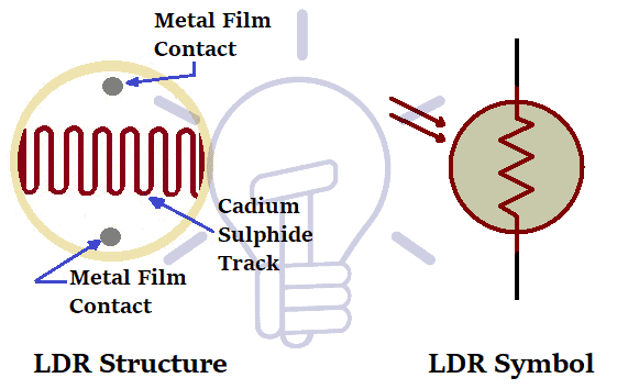
LDR is a light-controlled photo-resistor which is often used to detect light and change the circuit operation depending on the amount of the light sensed. An LDR is also called photoresistor or a cadmium sulfide cell. That is the reason it is called a light-sensitive device. They are generally made up of semiconductor material with high resistance. The resistivity of LDR is function of incident radiation.
The equation of resistance and radiation is represented by the equation:
R = A.E ^a
Here,
E = illumination
R = Resistance
A, a= constants
The value of “a” depends on the Cds used in the manufacturing process (ranges between 0.7-0.9).
- Related Project: Automatic Street Light Control System using LDR
Working Principle of LDR
Photoconductivity is a process in which the conductivity of material increases when light is absorbed by the surface. Light-emitting resistor works on the principle of photoconductivity.
Light-emitting resistors are a light-dependent device whose resistance is decreased when light falls on the device and increased in dark as well.
Whenever light falls on the device, the valence band electrons get excited to the conduction band. When lights with more energy fall on the device, a greater number of electrons get excited to the conduction band. In result, a large number of charge carriers are produced. Therefore, more current starts flowing through the device and hence the resistance of the device is decreased.
LDRs are generally non-linear device. The sensitivity varies with the wavelength of light incident on it. As soon as the constant voltage is applied on the circuit and intensity of light is increased, the current starts increasing. Based on the material used in the manufacturing of LDR, there are two types of light-emitting resistor namely Intrinsic photoresistor, Extrinsic photoresistor.
- Related Project: Public Street & Road Lighting – Illumination Design
Intrinsic Photoresistor
These type of LDRs are made up of pure semiconductor materials like silicon and germanium. Electrons from valence band get excited to conduction band when the amount of charge carriers is increased.
Extrinsic Photoresistor
These type of LDRs are made up of semiconductor materials doped with impurities called dopants. These dopants create another level, above the valence band filled with electrons. This reduces the bandgap and therefore less energy is required in exciting them. These kinds of photoresistors are generally used for longer wavelengths.
Construction of LDR
A light-sensitive material is deposited on an insulating substrate called ceramic. After that, ohmic contacts are made on either side of the area. Make sure that resistances of these contacts are less so that the resistance changes only due to the effect of light. The materials used for this purpose are generally cadmium sulfide.
LDRs are very cheap as compared to other light-sensing devices. They come in a variety of sizes which can be used for different purposes.
Go through the list of automatic LDR applications:
- It can be used in streetlights to sense lights
- It can be used in the burglar alarm circuit
- It can be used in camera lights
- It can be used in outdoor clocks and alarm clocks
Features of LDR:
- It consumes low power as compared to other light-sensing devices
- It is easy to interface with every electronic component even with micro-controller
- This component is highly reliable and cheap as compared to others
We hope you have got a good knowledge of LDR, it’s operation and working. Since we can’t use the fluctuating voltage to operate the LED array, we have used IC 7805 as a voltage regulator to maintain the output voltages at a constant value in our circuit. This IC is used to maintain the voltage fluctuations across the circuit. Let us discuss the working and specifications of the voltage regulator IC 7805.
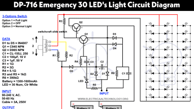
- Related Project: Emergency LED Lights Circuit – LED-716 LED Light Schematic
Voltage Regulator IC 7805
IC 7805 belongs to the series of fixed linear voltage regulators used to maintain the fluctuations in circuit. This voltage regulator IC helps you maintain the output voltage at a constant value.
The ratings of this 7805-voltage regulator IC is as follows:
- Input voltage ratings- (7v-3v)
- Current ratings – (1A)
- Output voltage ratings- (4.8 V to 5.2V)
Go through the below details to understand the pinouts of this IC:
- Pin 1- Input voltage PIN where unregulated voltage is given.
- Pin 2- Ground PIN
- Pin 3- Regulated output voltage
Components List
- Voltage regulator 7805
- Light Dependent Resistor (LDR) – 2MΩ
- IRF540 MOSFET
- BC548 Transistor
- High bright LEDs – 3V rated as15mA
- Red LED – 1
- 10KΩ Resistors – 3
- 1KΩ Resistor – 1
Related Project: Traffic Light Control Electronic Project using IC 4017 & 555 Timer
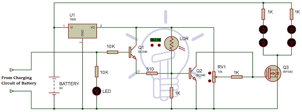
Automatic Emergency LED Light Circuit Diagram
Assemble the components as shown in the below circuit diagram. The automatic emergency LED light circuit can be designed in two parts. The first one is battery charging circuit which acts as an indicator circuit when the power supply is turned OFF.
The second circuit is an emergency light circuit that turns on the LEDs according to the light condition.
Working Principle of Emergency LED Light
The circuit works on the principle that as long as the power supply is available, the LEDs will not glow. As soon as the power fails, the white LED array connected to the MOSFET will glow based on the condition that if it is dark or bright outside.
Operation
When the main supply is active, at that time the battery is in charging state. As the supply cuts off, the circuit detects the power failure and the battery comes in action. Then the circuit operated on the power of a battery. Therefore, the Q1 transistor turns on and allows the current to flow through its collector to emitter. By which the LDR gets powered, and check whether the ambient light through it is LOW or HIGH.
If the ambient light across the LDR is LOW, the transistor Q2 turns ON and the LED array connected to it, starts glowing.
If the ambient light across the LDR is high, the transistor Q2 remains in OFF condition and the LED array connected to it remains OFF (even in the power failure condition).
Note: Make sure that there is no common connection between the AC and DC supply while giving connections to the circuit.
Features of Automatic LED Light Circuit:
- The cost of automatic LED light circuit is very less which makes it even more useful
- As circuit switches OFF the emergency lights according to the light condition, it helps you in energy consumption to a great extent.
Applications of Automatic LED Emergency Light:
- It can be used in rooms and shops to stay from a sudden power failure condition
- It can be used in security systems to tackle the sudden power failure problem
Bottom Line:
We have described the design of an Automatic emergency LED light circuit in the above discussion. We have also defined the use and working of LDR (Light-emitting resistor) in detail. We hope you have got a good knowledge of LDR working principle that will help you to understand the working of LDR in our Automatic LED emergency light circuit. We believe that now you will be able to design this highly reliable and low-cost automatic LED emergency light with ease on your own.
Related Projects: