Automatic Night Lamp Using Arduino
Automatic Night Lamp Using Arduino – Code, Working and Simulation
Automation basically means to invent a method which reduces or eliminate human efforts. In this tutorial, we are going to explain how to automate a night lamp via a simple interfacing of Arduino and Relay by using Proteus software. Automation is the need of the hour as the application ranges from boiler control with a simple thermostat to large industry management with a grand amount of input and output data. The complexity of the automation can vary from a basic” on/off “control to highly complex multivariable algorithms such as industrial automation system. The control systems for the automation purpose can either be open loop or closed loop meaning it can work either with a single input parameter or in response to the output fed as the input as in case of closed loop systems.
Like in the case of every technology automation also has its pros and cons:
Pros
- Increase in productivity
- Predictable quality (Quality Improvement)
- Increased robustness
- Great output consistency
- Reduction in human labour expenses
- Highly accurate
- Reduces human efforts in monotonous works
Cons
- Susceptible to security threats
- Development cost might excess beyond the prediction
- High setting up cost
- Cause of unemployment in many sectors
The pros mentioned far outweigh the cons and that is why the entire world is stepping into the era of automation.
In this tutorial we are trying to make a lamp turn on or off by itself when the circuit detects an appreciable change in the intensity of light and for achieving that we are going to use the two most common tools used for automation i.e. Arduino and Relay and interfacing along with the simulation would be achieved by the Proteus software.
- Related Project: Automatic LED Emergency Light Circuit
Components Required
- Arduino UNO
- Relay 5 Volts
- LDR (Light Dependent Resistor)
- Resistor 10K Ohms
- Transistor BC547
- DC Supply 5 Volts
- AC Supply 220 Volts
Software Required
- Arduino IDE
- Proteus
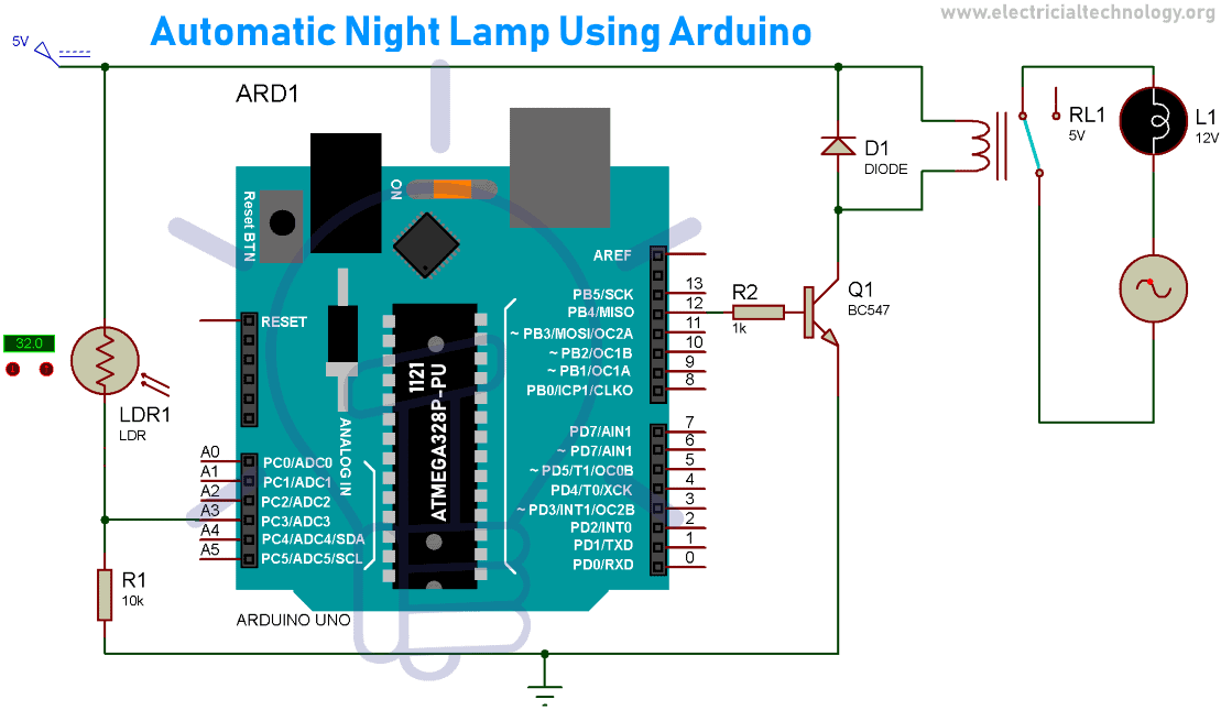
Automatic Night Lamp Circuit Diagram
Component Description
Arduino UNO
Arduino is basically a development board which is open source and primarily utilizes the Microchip ATmega328P microcontroller and is manufactured by Arduino.cc. The board comes with a set of input/output pins comprising of digital and analog which can be interfaced to different expansion boards and external circuits. The board comes bearing 14 digital pins along with 6 Analog pins which are utilized or made programmable with the help of an IDE (Integrated Development Environment). The program is burned via a USB cable type B.
Powering up methods for the board can be either by the USB cable or by connecting 12 volts dc supply. By the design and working point of view, it is not too different from its other family members namely Arduino Nano and Arduino Leonardo.
STK500 is still the original protocol for Uno to communicate. The major difference from its predecessors is that it does not make use of the FTDI (USB-to-serial driver chip).
- Related Post: What is Arduino and How to Program it?

Relay
Relay is an electromagnetic switch which can be operated electrically and made to turn on and off AC/DC appliances. It can be controlled even with a low voltage of 5 volts like the output provided by the Arduino pins. It consists of a coil with metal contacts on one side (low-voltage side) that can be magnetized and demagnetized to open or close the circuit attached on the other side (high-voltage side). High voltage side consists of a connector with 3 sockets namely common (COM), normally closed (NC) and normally open (NO). The relay comes in different ratings like 12V, 9V, 5V, and 3V.
- Related Post: How to Test a Relay? Checking SSR & Coil Relays
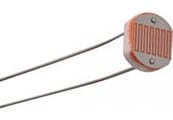
LDR
LDR (Light Dependent Resistor) is a variable resistance component that can vary its resistance value with the change in intensity of light and it works on the photoconductivity principle. The value of resistance decreases with increase in the intensity of light. It is used in light-sensitive detector circuits and light activated switching circuits.
LDR is made up of high resistance semiconductor that has resistance in mega ohms in absence of light while several hundred ohms in the presence of light.
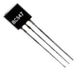
BC547 – NPN Transistor
A transistor is basically a semiconductor device which is employed to amplify or switch electronic signals and power. It is made up of semiconductor material and has 3 terminals to connect with an external circuit. In this circuit, we have used BC547 which is an NPN Bipolar Junction Transistor.
A small value of current at its base terminal controls a large value of current at its emitter and collector terminals. A fixed dc voltage is required at transistor terminals to operate in the desired region of its characteristic curves. Transistor, when used for amplification purpose, is kept biased so that it is partly on for all inputs and the amplified output signal is taken at the emitter. For switching applications, the transistor is biased so that it remains fully ON if signal at base terminal is present and it gets completely OFF in the absence of base signal.
Ratings
- VCEO =45 Vdc
- Ic=100mAdc
- VCBO =50 Vdc
- VEBO =6 Vdc
Software Description
Proteus
Proteus design suite comes under the category of proprietary software which is employed to perform electronic design automation. This software is very handy for the electronic design engineers and respective technicians for the purpose of creating schematics and the prints in electronic form termed as PCB layout. The software was developed in Yorkshire, England by Labcenter Electronics Ltd. and comes with multi-language support which are English, French, Spanish and Mandarin.
It is updated on a regular basis with new libraries consisting of advance components at regular intervals and can be easily added to the existing list of libraries.
This software is widely used because of its ability to simulate the circuits or micro-controllers. Simulation helps to understand the working and testing of the designed circuit without even making use of the physical components. Its user interface also gives an edge over other software out there in the market. Over 15 million components are available in the library section so users don’t need to waste time on creating footprints or components.
Arduino IDE
Arduino IDE is a software that can be used on various platforms. Hence, it’s a cross-platform application and was developed using the programming language java. It has a soul purpose of writing the sketch and uploading it on Arduino compatible boards. The supported languages are C and C++ which are a bit modified and depends upon the library being used. Various libraries are provided built-in in the software and other libraries can be downloaded from third-party vendors. The IDE uses a program called avrdude to convert the code into a file which has hexadecimal encoding which is loaded to the board with the help of a loader program which comes pre-installed in the board’s firmware.
Project Code
Explanation of Code
First of all, we define two global variables of integer type. Variable analogIN is used to denote an analog pin that will receive the analog value from the circuit and the second variable trigger denotes a digital pin that will supply a trigger output of sufficient voltage.
int analogIN = A3;
int Trigger = 12;
Baud rate is set to 9600 bits/sec which represents the data transmission rate. The pinMode() function is used to define state of the pin. Here we set the pin 12 as output and pin A3 as input. All these statements are written in the function void setup() and would run only once during the whole execution period.
void setup() { Serial.begin(9600); pinMode(analogIN, INPUT); pinMode(Trigger, OUTPUT); }
According to the circuit diagram, we have to read a particular data which is in the form of analog value from pin A3. For this specific task we have used the function analogRead() because the input generated from the circuit is an analog value hence this is the reason behind using analog pin and analog function.
Now, we get this analog value from the analog pin A3, then store its value in variable “value”.
This Variable will contain an integer value that will be in the range of 0 to 1234 and will vary according to the analog input. This is the 10-bit ADC value as Arduino comes with 10-bit ADC converter.
The value stored in the “value” variable is used for executing the conditional operator (if-else). Through this operator, we set the state of digital pin trigger as HIGH or LOW to turn on and off the lamp. The main advantage of printing the data stored in variable “value” is that we can associate the light intensity with a particular value and turn on the lamp at a desired intensity of light.
The code which is present inside the function “void loop()” will run repeatedly till the Arduino is being powered. Thus, to make sure the project is in working state at all instance one must make sure to give a 24/7 power supply to the Arduino Uno used here.
void loop() { int value = analogRead(analogIN); Serial.println(value); if (value < 692) { digitalWrite(Trigger, HIGH); Serial.println(“lamp is ON”); } else { digitalWrite(Trigger, LOW); Serial.println(“lamp is OFF”); } }
How to get the Hex File Location of the Code?
In your Arduino IDE click on File>Preferences and then in “Show verbose output” check both the options compilation and upload and upon the compilation of the code in the window below select and copy the location of the hex file and in Proteus double click on Arduino and paste the file location in the Program file option and click on OK. Now your circuit will be ready for simulation.
Simulation Video
Coming soon
Nigh Lamp Circuit Working
Now we will discuss the working of the circuit, here we have used a 5V DC supply (Arduino’s 5V) and connected a 10k ohm resistor and an LDR in a voltage divider circuit. The voltage which can be taken across the resistor or the LDR and fed into the analog pin of the Arduino, pin A3 in this case.
With the help of the code mentioned above, the board will be able to detect the analog input provided to it. This value read is in accordance with the intensity of the light which is detected by the LDR.
While we can check the coming value on the serial monitor to calibrate the circuit according to the intensity of the light. Hence we can change the condition in the conditional statement provided in the code to turn the lamp “ON” & “OFF” at a desired intensity of light, hence making it dynamic.
Now when the conditional statement is satisfied i.e. the light intensity falls down below the value provided by you (in ADC equivalent form) the board will generate a” HIGH” output at the pin 12 By “HIGH” it is meant that it produces 5V output as pin 12.
In this case a sufficient voltage is developed at the base of the transistor and the transistor starts conducting. As a result, the current starts flowing in the coils of the relay and it switches on which means the NO terminal is switched to an active state to which the lamp circuit has been connected to and upon the completion of the circuit the lamp turns “ON”.
The lamp turns “OFF” when the else condition in the code becomes true i.e. the intensity of light increases from the threshold value provided given by us. Hence, output at pin 12 becomes “LOW” and subsequently relay is turned OFF which turn the Lamp OFF.
Bottom-line:
We all want to ease our lifestyle, and here what the automatic night lamp is doing. You don’t even need to turn ON or OFF the night lamp. As it automatically turns ON and OFF according to the intensity of light falls. When its day time the Lamp remains in off state as its getting dark over the sensor the lamp turns ON. The project will help you to design the same, using basic electronic components. We have also explained the code so that it won’t be difficult for you to get started with the Arduino.
Related Projects:


