Cable and Wire Tester Circuit Diagram
Multi Wire and Cable Electronic Tester Circuit Project
Cable testers are electronic devices used for testing electrical and electronic connections and strength in signal cables or different wired assemblies. They are generally used for checking of path connectivity, and it also checks the improper wiring. You can use a cable tester device to check the communication strength of cable from the source to destination.
Nowadays, along with the advancement in technology, advance cable testers are present in the market with improved features and quality. Advanced cable detectors can measure different cable properties such as resistance, interference, noise, and signal attenuation. Simple cable testers were discovered as a basic tester.
Cable testers are further divided into different types. In this article, we will be discussing the design process of the cable tester circuit along with its working and application. Before that, let us see the types of cable tester and their different usage.
Related Posts:
Basic Tester:
A phase tester or basic tester is a straightforward instrument which is operated on battery. This basic cable tester is easy to use and portable in nature. It has one or more than one Voltage indicators, a source of electric current, and besides it also has a scanning or switching arrangement for checking of different conductors one after the other. It may also contain a micro-controller and a display for automating purpose of the process of testing and showing the results.
You can connect the cable tester device to both the ends of the cable simultaneously, or there may be a separation between the indication and current source for allowing the injection of a test current at one end and detection of the results at the other. Here are two words Modular connectors and Ethernet.
If you are familiar with them, then it’s well and good, but if not, you should have a glance at them.
Modular Connectors:
Modular connectors were developed for use on Bell system in 1960s (It was a system of companies which was led by Bell telephone company providing telephone services to Canada and US). It is a kind of electrical connector for cords and cables of different appliances or electronic devices like telecommunication equipment’s, Audio headsets and computer networking.
Ethernet:
It is a family of computer network technologies which is generally used in LAN, MAN, and WAN.
A cable tester is generally used for checking whether the connections in the cable are intended or not. When there is a missing unintended connection, then it is called “open.” When unexpected connections are found then, it is called as ‘’short’’. Testing is performed in two different phases. In the first phase, it is checked that the intended connections are good which is known as Open test, while in the second phase it is verified that there are no unintended connections and is known as Short test.
Two Common Ways for Connections Test:
- Continuity Test
- Resistance Test
Continuity Test – Electric Current is passed in all the attachments; if the current is there in all the connections then only it is called as good. It is performed by using a battery and a light bulb.
Resistance Test – In this test, a known current is passed in the connections and after that voltage is measured and compared with the expected value.
Two Critical Methods for Testing Short–Circuit
- Low Voltage Test
- High Voltage Test
Low Voltage Test – In this test a little power and the small voltage source is connected between two conductors. Then the amount of current is measured, if there is no current, then the conductors are considered as isolated conductors.
High Voltage Test – In this test a top voltage source (about several 100 volts) is connected. An increased voltage will make the test more likely to find nearly shorted connections.
Types of Tester
Signal Tester
Comparatively more powerful cable testers can measure the properties of the cable-related to signal transmission which includes the DC resistance of the cable, the attenuation (i.e., loss of signal) of a message at one or more than one frequencies, and a measure of the isolation between multiple pairs of a cable or cross-talk.
Optical Signal Tester
Optical cable testers contain a source of visible light and are also a connector con with the visual cable installation.
Network Cable Tester
A basic network cable tester consists of a source of electric current and a measuring device. They are correctly connected between the computer and the server.
Four Types of Network Cable Testing
- Network Channel Testing – It measures the performance of the network between workstation and hub.
- Permanent Link Testing – In this testing when cable installation takes place, an installer or setup team pulls the cable, terminate them on the patch panel and keystone jacks. Hence the performance of permanent link is tested.
- Continuity Testing – It is one of the most basic forms of testing that determines whether you can establish a connection between two points or not.
- Wire mapping – By using wire mapping tester we can get an idea of how the cable is wired or paired.
CAT 5, CAT5e, CAT6 are network cables used as cable testers for testing in computers. Since different kinds of data are transmitted over network cables, it is necessary that it connects appropriately between the computer and the server.
This is all about the network cable testers. Now in this project, we will be using the IC 4017 as a counter device.
Components Required for Wire Tester
- IC-4017
- 555 timer IC
- Resistors (10k-2, 2.2k-2,500k-4)
- LED
- Power supply- 9V
- Breadboard
- Capacitors (10uf-1, 10nf-1)
- Connecting wires
IC 4107:
IC 4017 is a decoder circuit that works well with the low range counting applications. This counter application is used in the channel for creating LED effects. This 16 Pin CMOS decade counter is easy to use and interface with 555 timer IC.
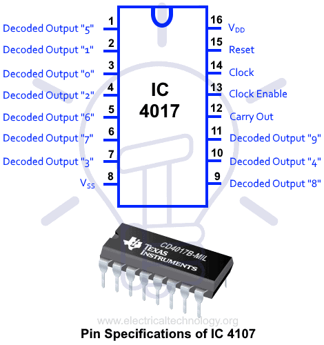
Pin Specifications of IC 4107:
| PIN | Function & Description |
| Pin-1 | It is output 5 and goes high when the counter reads five counts. |
| Pin-2 | It is called output 1 and goes high when the counter reads 0 counts. |
| Pin-3 | It is output 0, and It goes high when the counter reads 0 counts. |
| Pin-4 | It is output 2 and goes high when the counter reads two counts. |
| Pin-5 | It is the output 6 and goes high when the counter reads six counts. |
| Pin-6 | It is output 7 and goes high when the counter reads seven counts. |
| Pin-7 | It is output 3 and goes high when the counter reads three counts |
| Pin-8 | It is the Ground pin of IC |
| Pin-9 | It is output 8 and goes high when the counter reads eight counts. |
| Pin-10 | It is output 4 and goes high when the counter reads four counts. |
| Pin-11 | It is the output 9 and goes high when the counter reads nine counts |
| Pin 12 | Can be used to cascade another IC or counter to increase efficiency |
| Pin 13 | It is the disable pin |
| Pin 14 | It is the clock input |
| Pin 15 | This is the reset pin which is kept Low during regular operation |
| Pin 16 | This is the VCC Pin |
Cable Tester Circuit Diagram
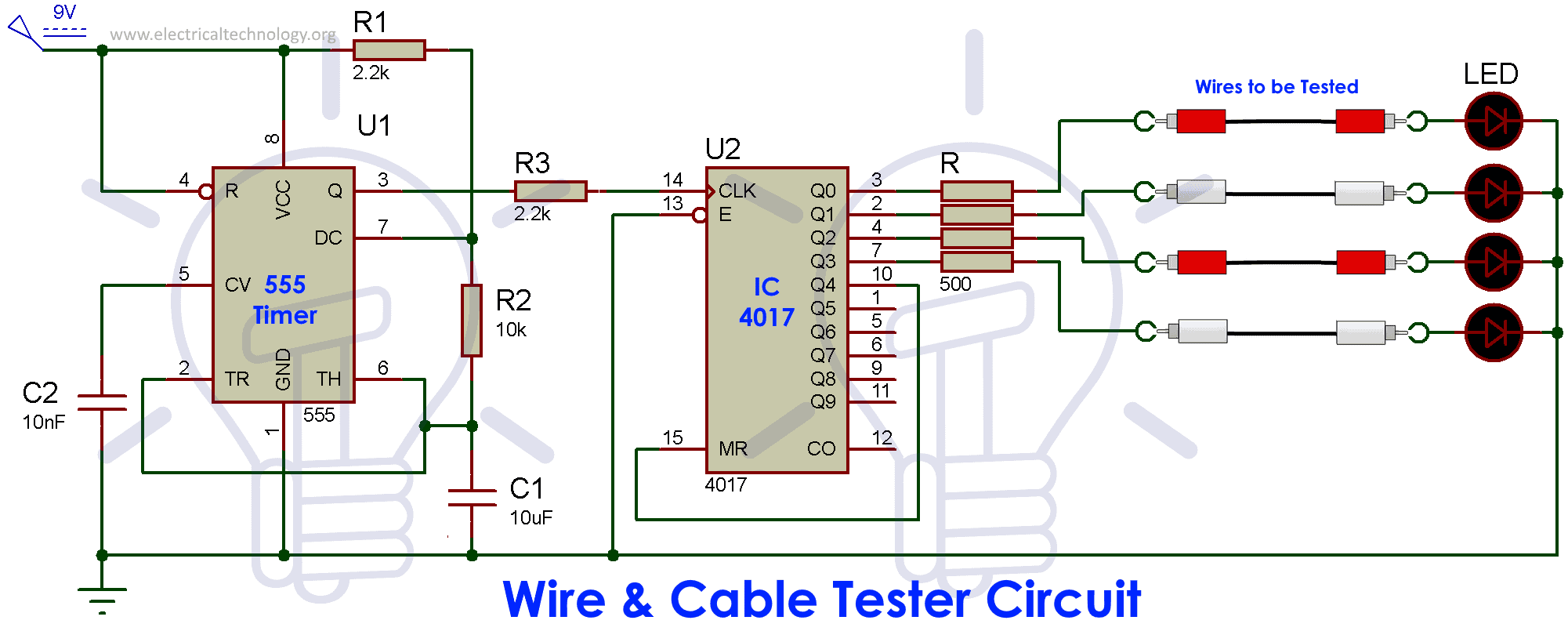 Note that we are using 555 timer IC to control the circuit functioning. The working and features of 555 timer IC have been discussed in our previous articles. Now you are aware of the features of IC-4017 after reading the above discussion. Now, gather the following components to assemble the cable tester circuit.
Connect the components as discussed below:
- Step1-Connect the clock pulse through 555 timer IC to pin no-14 of IC 4017
- Step2-Connect 5th output (Q4) to the reset pin for reset.
- (As soon as 5th output Q4 goes high, it resets the IC and make Q0 high again)
Working of Cable Tester
In this circuit 555 timer IC is used in astable mode to generate a clock signal. Frequency of clock pulse is dependent on two resistors R1 and R2 measuring 2.2 and 10-kilo-ohms respectively, and capacitor C1 of 10 uf. Therefore, the speed of blinking led is dependent on this frequency.
Here, we have used four wires to show how wire cable tester works. If all cables are non-defective, then it allows the passing of current, and hence the LED connected to the other end goes HIGH (glows). If any defect is present, then the respective LED will not glow. So, we can say that some error must be present on the cable. Hence after completing the test, we get the result that whether the cable is defective or not. We have a multifunction network cable tester (RJ45). It is very much convenient to use.
Applications of Cable Tester:
- RJ11 cable tester is used for telephone wires and for network cable RJ45 cable tester is used.
- It conducts two tests, i.e., master and remote that can take a role in analysis easier.
- It can be used for checking the improper connection wires or short-circuit point in the cable.
Bottom line:
Cable tester is of great use for testing wire faults. We have used IC 4017 also we have discussed the working of IC 4017 as counter to display the output. We have used 555 timer IC to generate the PWM signal for 4017 IC. Both the major components are discussed along with their working in this article. We hope that now you will be able to design this easy to use cable tester without any difficulty.
Related Posts:


New tec
Link not open
Kindly send us electrical engineer design details
Automations and home automation design details required