USB Propeller LED Fan Clock – Circuit Diagram & Project Code
USB LED Light Fan Analog Clock Using Arduino NANO – Project Code & Circuit Diagram with Time Setting Feature
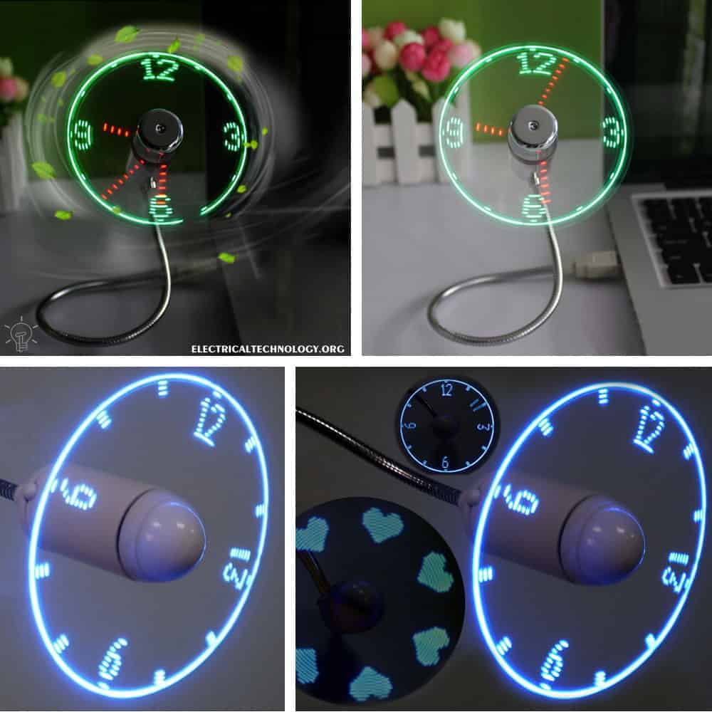
If you have watched the video of the famous gadget of Mini USB LED light Fan clock, get ready as we will design the same LED light analog clock based on Arduino NANO, hall sensor, resistors, battery, DC motor and LEDs.
The LEDs will rotate in circular motion and show an analog clock in propeller display with all the three hands for hour, minute and second respectively as well as the rounded (circular) shape like an ordinary wrist or wall clock.
The best thing in this project is that you can change the time setting for both minutes and seconds via uploading the source code to the Arduino NANO via USB cable. Let’s see how to do it.
Check the Gadget of LED Light FAN Clock
Required Components:
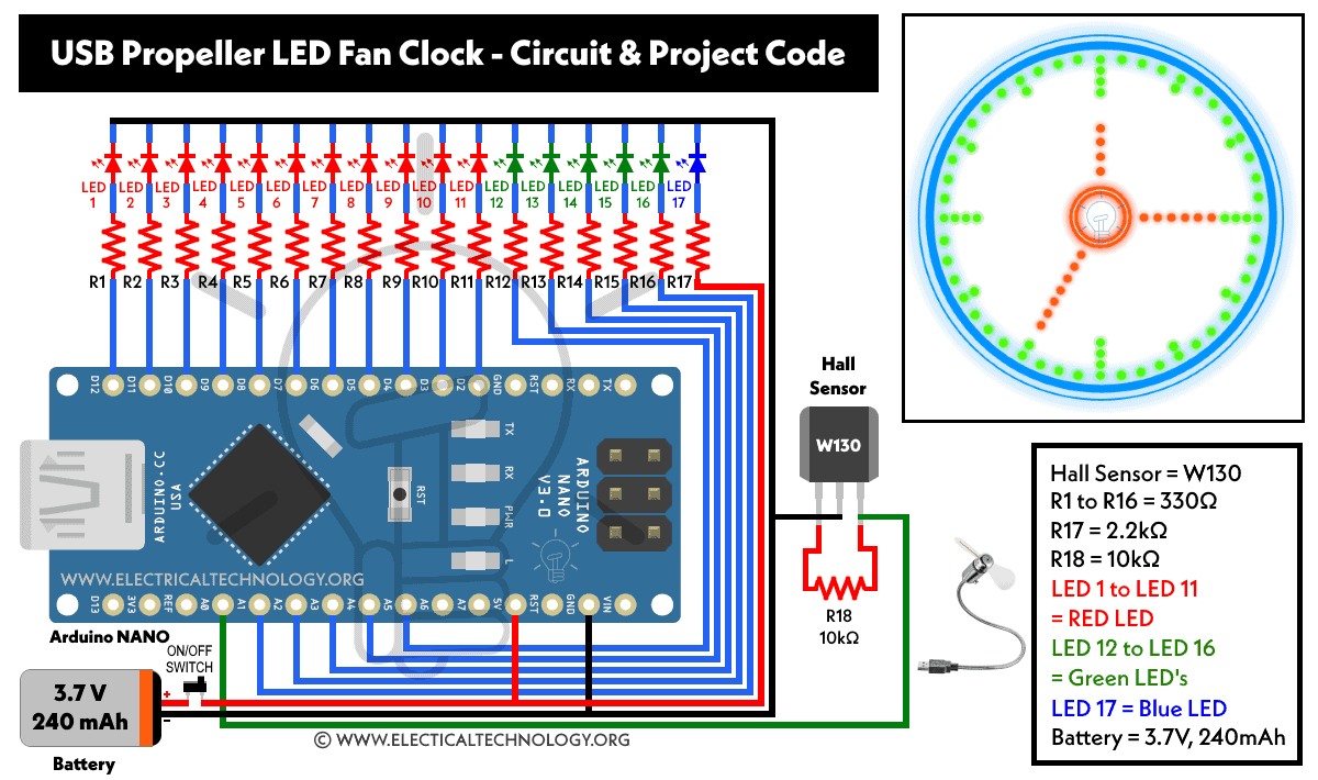
- Arduino NANO
- Hall Sensor W130
- R1 to R16 = 330Ω
- R17 = 2.2kΩ
- R18 = 10kΩ
- LED 1 to LED 11 = Red Light
- LED 12 to LED 16 = Green Light
- LED 17 = Blue Light
- Battery = 3.7V, 240mAh (9V to 12V in case of powerful motor for high speed operation)
- Switch = ON / OFF Single Pole (Slide Toggle)
- Other components: PCB board, Toy DC motor, wires & cables, soldering iron etc.
Wiring & Circuit Diagram
Following the is the given circuit diagram for USB propeller LED fan analog clock. If you want to make the same project with a time setting feature, check the second circuit diagram given in the bottom of this post.
Procedure:
- Cut a small piece of PCB board according to the circuit.
- Insert a Green LED into the holes with the long leg on the left side. Now from the copper side, bend its legs to one side (Green LED’s i.e. LED 12 – LED 16 via R12 to R16 and A5 to A1 respectively).
- The same way, insert the remaining Red LED’s (LED 1 – LED 11 via R1 to R11 and D2 to D12 respectively).
- Insert the Blue Led above the green led as shown in fig (Blue LED 17 via R17 and A7). Connect R17 as 2.2kΩ and join the cathode of this LED to the cathode of other LED’s. Now, connect the positive leg of this Led to one end of the resistor R17 and the other end to the Arduino +5V pin.
- All the cathode connections of the LED’s are joined together. Cut off the excess leads if needed.
- Now insert the resistors and bend its leads the same as you did for LED’s. Cut the extra leads accordingly.
- Now solder the components according to the circuit diagram.
- Now, solder connectors to the Arduino NANO.
- Connect a wire from LEDs common cathode to the Arduino GND pin.
Connect wire from resistors to Arduino Digital pin “D” and Analog pin “A” as follows:
- R1 to D2
- R2 to D3
- R3 to D4
- R4 to D5
- R5 to D6
- R6 to D7
- R7 to D8
- R8 to D9
- R9 to D10
- R10 to D11
- R11 to D12
- R12 to A1
- R13 to A2
- R14 to A3
- R15 to A4
- R16 to A5
Connect Hall sensor as follows:
- Output pin to Arduino A0 pin.
- VCC pin to Arduino +5V pin.
- Sensor ground pin to Arduino GND Pin.
As a final touch:
- Connect the 3.7V, 240mAh battery according to the circuit and don’t forget to add a single pole toggle slide switch on the positive lead for ON and OFF operation of the circuit.
- Now, Mount the whole project to a chipboard with the help of a toy DC motor. Keep in mind that if you use a powerful motor for high speed, you may use a 9V to 12V battery instead.
- Finally, upload the project code (given below) viva USB cable and Switch ON the circuit. The fan will show the clock in LED light while in propeller motion.
Project Code
You can make the necessary changes to the following source code of USB Led fan clock and upload to the Arduino NANO through USB cable if needed.
Code via: hobbyprojects
int LED1 = 2;
int LED2 = 3;
int LED3 = 4;
int LED4 = 5;
int LED5 = 6;
int LED6 = 7;
int LED7 = 8;
int LED8 = 9;
int LED9 = 10;
int LED10 = 11;
int LED11 = 12;
int LED12 = A1;
int LED13 = A2;
int LED14 = A3;
int LED15 = A4;
int LED16 = A5;int sensorPin = A0;
int minuteSensor = A7;
int hourSensor = A6;unsigned int n,ADCvalue,propeller_posn;
unsigned long previousTime = 0;byte hours = 12; // set hours
byte minutes = 15; // set minutes
byte seconds = 00; // set secondsint val;
void setup()
{
pinMode(LED1,OUTPUT);
pinMode(LED2,OUTPUT);
pinMode(LED3,OUTPUT);
pinMode(LED4,OUTPUT);
pinMode(LED5,OUTPUT);
pinMode(LED6,OUTPUT);
pinMode(LED7,OUTPUT);
pinMode(LED8,OUTPUT);
pinMode(LED9,OUTPUT);
pinMode(LED10,OUTPUT);
pinMode(LED11,OUTPUT);
pinMode(LED12,OUTPUT);
pinMode(LED13,OUTPUT);
pinMode(LED14,OUTPUT);
pinMode(LED15,OUTPUT);
pinMode(LED16,OUTPUT);pinMode(sensorPin,INPUT_PULLUP);
if(hours == 12)
hours = 0;//****************************************
// Uncomment these lines for IR sensor testing
/*
Serial.begin(9600);while(1)
{
ADCvalue = analogRead(minuteSensor);
Serial.print(“minuteSensor “);
Serial.println(ADCvalue);ADCvalue = analogRead(hourSensor);
Serial.print(“hourSensor “);
Serial.println(ADCvalue);Serial.println();
delay(1000);
}
*/
//****************************************
}void loop()
{
val = digitalRead(sensorPin);while (val == LOW)
{
val = digitalRead(sensorPin);
}if (millis() >= (previousTime))
{
previousTime = previousTime + 1000;
seconds = seconds+1;
if (seconds == 60)
{
seconds = 0;
minutes = minutes+1;
}
if (minutes == 60)
{
minutes = 0;
hours = hours+1;
}
if (hours == 12)
{
hours = 0;
}
}propeller_posn=30;
n=0;while(n < 60)
{ADCvalue = analogRead(minuteSensor);
if(ADCvalue < 500)
{
minutes = propeller_posn;
seconds = 0;
}ADCvalue = analogRead(hourSensor);
if(ADCvalue < 500)
{
hours = propeller_posn/5;
seconds = 0;
}drawMinuteMarker();
if ((propeller_posn==0) || (propeller_posn==5) || (propeller_posn==10) || (propeller_posn==15) || (propeller_posn==20) || (propeller_posn==25) || (propeller_posn==30) || (propeller_posn==35) || (propeller_posn==40) || (propeller_posn==45) || (propeller_posn==50) || (propeller_posn==55))
drawHourMarker();if ((propeller_posn==0) || (propeller_posn==15) || (propeller_posn==30) || (propeller_posn==45))
drawQuarterMarker();if((propeller_posn == hours*5) || (( propeller_posn == 0 ) && (hours == 0)))
drawHoursHand();if(propeller_posn == minutes)
drawMinutesHand();if(propeller_posn == seconds)
drawSecondsHand();delayMicroseconds(100); // for LED pixel width (change the value according to motor speed. Increase for low speed, decrease for high speed motor)
displayClear();
drawInner_Circle();
delayMicroseconds(450); // for the gap between LED pixels/minutes markers (change the value according to motor speed. Increase for low speed, decrease for high speed motor)
n++;
propeller_posn++;
if(propeller_posn == 60)
propeller_posn=0;
}val = digitalRead(sensorPin);
while (val == HIGH)
{
val = digitalRead(sensorPin);
}
}//=========================
void displayClear()
{
digitalWrite(LED1,LOW);
digitalWrite(LED2,LOW);
digitalWrite(LED3,LOW);
digitalWrite(LED4,LOW);
digitalWrite(LED5,LOW);
digitalWrite(LED6,LOW);
digitalWrite(LED7,LOW);
digitalWrite(LED8,LOW);
digitalWrite(LED9,LOW);
digitalWrite(LED10,LOW);
digitalWrite(LED11,LOW);
digitalWrite(LED12,LOW);
digitalWrite(LED13,LOW);
digitalWrite(LED14,LOW);
digitalWrite(LED15,LOW);
digitalWrite(LED16,LOW);
}void drawMinuteMarker()
{
digitalWrite(LED16,HIGH);
}void drawHourMarker()
{
digitalWrite(LED15,HIGH);
digitalWrite(LED14,HIGH);
}void drawQuarterMarker()
{
digitalWrite(LED13,HIGH);
digitalWrite(LED12,HIGH);
}void drawHoursHand()
{
digitalWrite(LED1,HIGH);
digitalWrite(LED2,HIGH);
digitalWrite(LED3,HIGH);
digitalWrite(LED4,HIGH);
digitalWrite(LED5,HIGH);
digitalWrite(LED6,HIGH);
digitalWrite(LED7,HIGH);
}void drawMinutesHand()
{
digitalWrite(LED1,HIGH);
digitalWrite(LED2,HIGH);
digitalWrite(LED3,HIGH);
digitalWrite(LED4,HIGH);
digitalWrite(LED5,HIGH);
digitalWrite(LED6,HIGH);
digitalWrite(LED7,HIGH);
digitalWrite(LED8,HIGH);
digitalWrite(LED9,HIGH);
}void drawSecondsHand()
{
digitalWrite(LED1,HIGH);
digitalWrite(LED2,HIGH);
digitalWrite(LED3,HIGH);
digitalWrite(LED4,HIGH);
digitalWrite(LED5,HIGH);
digitalWrite(LED6,HIGH);
digitalWrite(LED7,HIGH);
digitalWrite(LED8,HIGH);
digitalWrite(LED9,HIGH);
digitalWrite(LED10,HIGH);
digitalWrite(LED11,HIGH);
}void drawInner_Circle()
{
digitalWrite(LED1,HIGH);
delayMicroseconds(30);
digitalWrite(LED1,LOW);
}
How to Change the Time Setting in LED Fan Clock?
For Basic IR Receiver with the Main Circuit
Components Required:
- R19 & R20 = 10k
- IR Phototransistor LED (near LED#13 for Minute Setting)
- IR Phototransistor LED (near LED#16 for Hour Setting)
Just connect the R19 with first IR LED (near LED#13 for minute setting) and R20 with second IR (near LED# 16 for hour setting). Connect the common of IR LED’s and both resistors to the GND and 5V pin of Arduino NANO respectively. Finally, connect the jumper wire from A7 pin to between R19 and second IR. Do the same for the A6 pin to R20 and first IR.

For Basic IR Remote Control Transmitter
Components Required:
- 9V Battery
- Battery snap connector
- IR LED (Infrared Led)
- 1kΩ resistor
- Tact switch
- PCB Board
To make a simple IR remote control transmitter to set and control the time setting features in the USB LED fan clock, just connect all the components in series (i.e. 9V battery, IR LED, 1k ohm resistor and a tact switch on the positive terminal). This transmitter will be used to place and face the LED#13 and LED#16 to adjust the time.
The following code is used to change and adjust the hour and minute spindle (minute and hour hands in ordinary wall clock and analog watches) of analog USB led fan clock.
Check the Output of IR Detector circuit using Arduino Serial Monitor. For example, reading with normal room light is > 500 and reading with IR light is < 500. So, you can change the code or values here according to the sensors used.
propeller_posn=30;
n=0;while(n < 60)
{ADCvalue = analogRead(minuteSensor);
if(ADCvalue < 500)
{
minutes = propeller_posn;
seconds = 0;
}ADCvalue = analogRead(hourSensor);
if(ADCvalue < 500)
{
hours = propeller_posn/5;
seconds = 0;
To set the minutes hand, point the IR remote to the minute marker and press the remote button. To set the hour hand, point the IR remote to the hour maker and press the remote button.
Watch the Video:
Resources:
Kits & Components for this Project
Related Posts:
- What is Arduino and How to Program it? Arduino Programming
- Early Flood Detection System Using Arduino – Source Code
- Distance Measurement Using Arduino and Ultrasonic Sensor
- Variable Power Supply Using Arduino UNO – Circuit and Code
- Automatic Doorbell with Object Detection By Arduino
- Automatic Night Lamp Using Arduino
- Arduino PWM Programming and its functions in Arduino
- Arduino Serial: Serial Communication by Arduino
- Automatic Bathroom Light Switch Circuit Diagram and Operation
- Automatic Plant Watering & Irrigation System – Circuit, Code & Project Report
- Simple Cell Phone Charger Circuit Diagram – 5V from 230V AC


