What is Voltage? its Unit, Formula, Types & Applications
What is Voltage? Electric Potential Difference and EMF Definition & Applications
You must have heard of the voltage, current & power that is associated with electricity. It is one of the basic fundamental parameter of electricity. The overhead transmission lines that possess very high voltage used to transmit power over long distance to load center (cities, homes & industries).
Any electrical power source such as batteries has its voltage mentioned on its casing such as 12V car batteries or 1.5V batteries used in gadgets. The electrical sockets in our home does provide 120/220 voltage which is supplied from utility poles.
You need to know about the voltage because it is essential for any electrical equipment to be powered by the power source having the required voltage ratings that it’s designed for. Every electrical equipment has its voltage requirement mentioned on its nameplate or its manual.
Equipment designed for 220 volts won’t operate from a 12v supply & equipment designed for 12 volts will get damaged if connected with 220v supply. Apart from that, voltage has types & you must be able to differentiate which one is suitable for a specific device.
Related Posts:
- What is Electric Current, its Unit, Formula, Types & Applications
- What is Resistance? Resistivity (ρ) & Specific Resistance Ω.
- What is Electrical Power? Types of Electric Power and their Units
Before understanding the voltage, we need to understand the charge.
Electrical Charge
The sub atomic particles existing in an atom known as proton & electron are given arbitrary names positive charge & negative charge respectively. “The opposite charges attract each other”. In other words, the electron & proton attract each other.
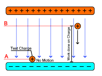 Suppose, two bars made of positive & negative charged particles & a positive test charge is placed on top of the negative bar at point A. The distance between test charge & negative bar is zero. If i let go of the test charge, there will be no movement.
If i move the charge in opposite direction (toward the positive bar) & increase the distance between them, the work done in moving the charge from point A to point B will convert into potential energy that is stored in it. If I let go of it, the test charge will accelerate towards the negative bar.
 This analogy explains the voltage where the voltage is the potential energy that corresponds to the distance between test charge & positive bar. In first case, there was no distance between them & the charge does not move which means if there is no voltage, the charge (current) does not flow in a conductor.
While the second case suggests that there is some voltage which forces the charge to move in a specific direction. The voltage is the pressure or force that pushes the current inside a conductor same as the force experienced by the negative charge.
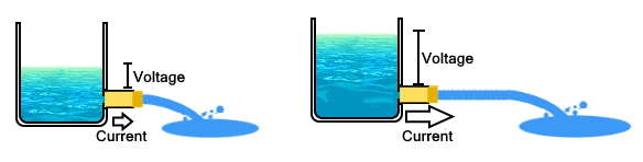
We can also use water analogy for understanding. Suppose, there is a tank of water that has a hole in its bottom so that water can flow out. The level of the water inside the tank represents the voltage & the amount of water flowing out represents current.
If the level of water inside the tank is very low, there will be low pressure exerted on the water flowing out. Therefore the amount of water flowing out in a unit time will be low. If the water level is high, it will exert high pressure, thus amount of water flowing out will increase. The same idea is used in voltage, where the voltage is the pressure that flushes the current in an electrical circuit. Greater the voltage greater will be the current flow though the circuit.
- Related Post: Difference Between Electric Current and Electric Charge
What is Voltage?
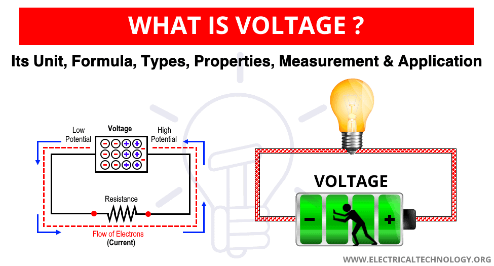
In electrical circuit, voltage is the force or pressure that is responsible for pushing the charge in a closed looped conductor. The flowing of charge is called current. The voltage is the electric potential between two points; the greater the voltage the greater will be the current flow through that point. It is denoted by letter V or E (used for representing electromotive force).
Voltage is also known as Electric Pressure, Electric Tension or Electric Potential Difference. There is a little bit difference between Voltage and EMF (Electromotive Force).
Unit of Voltage
The unit of voltage is volt named after Italian physicist Alessandro Volta who invented the first battery (chemical battery to be more precise).
Volt is defined as “the potential difference between two points that allows a current of 1 ampere through it and dissipates 1 watt of power between these points”.
In other words, a “Volt” is the potential difference which moves one joule of energy per coulomb charge between two points.
V = J / C = W / A … in Volts
Where:
- V = Voltage in “Volts”
- J = Energy in “Joules”
- C = Charge in “Columbus”
- W = Work done in “Joules”
- A = Current in “Ampere”
For more details, check the latest post about “What is Volt (V)? Unit in Electrical Engineering and Physics“.
- Related Post: Difference Between Current and Voltage
Electromotive Force & Potential Difference
The potential difference or voltage & EMF are interchangeable but there is a little difference between them. You see, the voltage of a power source such as the batteries drops when they are connected with a circuit having load (resistance).
The voltage drop is due the internal resistance inside the batteries. This reduced voltage is known as potential difference which depends on the connected load while the EMF (electromotive force) is the unloaded voltage of the battery or power supply.
The potential difference is always less than the EMF and The EMF is the maximum voltage the battery can supply.
Related Posts:
How Voltage is Generated?
The voltage is generated using various methods such through chemical reactions inside batteries, solar radiation in photovoltaic cells, & using magnetic induction in turbine generators. In either case, the power source generates potential difference across its terminals that can push the charge to flow through the circuit.
Voltage Polarity
The voltage polarity is a very important point to understand the voltage. As we know, the voltage is an electric potential difference between two points. The difference suggests which of the two points has the highest potential. In other words, the voltage at a point is taken with a reference to another point.
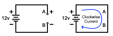 The given circuit has a break at points A & B where the voltage between them is equal to the 12 volts. The voltage at point A is +12 volts with respect to B while the voltage at point B is –12 volts with respect to A. This polarity is assigned by the terminals of the power source. Suppose, we close the circuit, the current will start to flow in clockwise direction from the positive terminal to negative terminal.
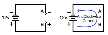 Now if we swap the terminals of the source, the voltage polarities at points A & B also reverses. If we connect the circuit close, the current will start flowing in anticlockwise direction. The direction of the current flow in a circuit depends on the voltage polarities of the source.
In Alternating current, the voltage polarity swaps multiple times on its own. Therefore, the direction of the current also reverses multiple times.
As we have discussed, the electric current flows from high potential to low potential, as shown in these circuits. But the definition of electric current is the flow of electrons (negative charges). It is supposed to flow from the low potential (negative terminal) to the higher potential (positive terminal) of the battery. The former is called conventional current while the latter is called electron current.
The idea of conventional current i.e. the flow from high potential to low potential was established way before the discovery of electron current & multiple rules were established based on conventional current. Apart from that, it does not matter what direction you assign to it, as long as it remains consistent.
- Related Post: What Happens if a Battery is Connected to the AC Supply?
Types of Voltages
The voltage has various types according to the nature of is polarity & voltage levels.
DC Voltage
The direct current (DC) is a uni-directional current that flows in only one direction. Usually the source of DC supply is batteries where the polarities are clearly mentioned on it. Such sources can store electrical energy in DC form. It has fixed polarities i.e. positive & negative. Apart from ± signs, the DC voltage is denoted by dash with 3 dots (⎓) symbol.
Since the DC voltage pushes the current in only one direction, you should be careful when connecting the load using correct polarities. Reversing the polarities will damage the circuit.
AC Voltage
In Alternating current (AC), the current direction changes continuously due to the continuous change in voltage polarities. The voltage supply in our home’s outlets has 50/60 Hz supply i.e. it swaps its polarities 100/120 times in a second. It has no consistent polarities which is why you won’t see any + or – sign on the outlets. Therefore, the load can be connected in either position. Swapping the terminals of equipment will not affect its operation. The AC voltage is denoted by a wave symbol ~.
Any equipment designed for AC cannot be operated using DC voltage & the opposite is also true. The voltage type is clearly mentioned on equipment that it is designed for.
Extra Low Voltage ELV (<70)
The extra low voltage or shortly known as ELV is range of voltage below 70 volts. Such level of voltage is not harmful human body. It is specifically used to eliminate the hazard of electrical shock. It is used in pool lighting, spa, & battery operated equipment.
Low Voltage LV (70 – 600 v)
The low voltage is the range of voltages that is above ELV & falls below 600v range. This voltage is usually supplied to consumer’s home & industries. The outlets in our homes supply 110/220 volts. It is not recommended to touch live wires having such voltages. Touching such voltage will give you shock & push you away if you are lucky. However, it may prove fatal in wet conditions so always be careful around it.
Medium Voltage MV (600 – 35 KV)
The medium voltage ranges falls below 35KV & these voltages are not usually used for consumption. It is mostly used for transmission between substations & utility poles near our homes. These voltages are very dangerous & are very fatal.
- Related Post: What Happens When an AC Line Touches a DC Line?
High Voltage HV (115,000 – 230,000 KV)
The high voltages range between 115 KV & 230KV. These voltages are used for power transmission between cities and from generation station to load substations.
Extra High Voltage EHV (345,000 – 765,000 KV)
The extra high voltage ranges between 345KV & 765 KV & they are used for power transmission over very long distance. The voltage needs to be increased to transmit over larger distances. Increase in voltage decrease the line losses occurring due to the current.
Ultra High Voltage UHV (765,000 – 1,100,000 KV)
These voltages are very high & are used for power transmission over very long distances.
High Voltage Direct Current (HVDC)
The high voltage direct current or shortly known as HVDC is a range of DC voltages used for efficient power transmission over long distance. as the name suggest, it is DC voltages in very high ranges. The benefit of using HVDC instead of HVAC is that it is cheaper, having very low losses for transmitting power from remote generating station to load centers that are over 600 km or 400 miles away. It is also used for underground or underwater power transmission from offshores wind farms.
How to Calculate Voltage?
Voltage can be calculated in different scenarios which depend on the available related quantities such as current in amps, power in watts and resistance in ohms etc. For a clear explanation, let see the following solved examples.
Example 1:
Calculate the value of voltage drop across a 6Ω resistor if the value of flowing current is 2A in it.
Solution:
According to Ohm’s law:
V = I x R
Putting the values
V = 2A x 6Ω
V = 12 V
Example 2:
Determine the value of supply voltage if 16A current is flowing in a 1920W water heater element.
Solution:
We know that
V = P ÷ I
Putting the values:
V = 1920W ÷ 16A
V = 120 V
Example 3:
Find the value of required voltage to glow a light bulb having 10W and 10Ω resistance.
Solution:
The derived equation from P = V x I (where putting I = V ÷ R).
V = √(P x R)
Putting the values:
V = √(10W x 10Ω)
V = √(100)
V = 10 V.
How to Measure Voltage?
We use multiple instruments to measure line parameters such as current, voltage , & resistance etc. The instrument used for measuring voltage between two points is known as Voltmeter.
Voltmeter is either analog or digital. The evolution of technology makes it easier to read & offer a precise reading through the digital voltmeter. Nowadays, the digital voltmeter is used because it eliminates the human error as well as it can be more precise. We use the readings of the voltmeter to troubleshoot any electrical system.
Expect the voltmeter, a potentiometer and digital or analog multimeter is also used to measure the voltage across an enlacement. There is voltage mode (for AC and DC) in a multimeter and the leads are placed in parallel with the element where the voltage across it needed to be measured.
Note:
- Always connect the voltmeter across the voltage source in Parallel setup.
- Keep in mind that voltmeter is connected in series to measure the electric current.
- Always choose the lower voltage level (by moving the volt-meter knob to the lower level i.e. 50V, 100V etc) and then increase to the desired voltage level while measuring the voltage.
- Select the AC and DC in a volt-meter (by moving the AVO meter knob to AC/DC symbols printed on it) while measuring the different voltage levels for AC and DC circuits respectively.
Common AC & DC Voltage Levels
The typical voltage level of different electrical devices and appliances are known as common voltage. Following are some common voltage levels for both AC and DC applications in different countries.
DC Voltage Levels
- Most common solar panels are available in 12V. The value of each solar cell is about 0.5V to 0.6V. These cells are arranged nearly always in series to achieve the desired 12V system.
- The batteries used in auto and electric vehicles is 12V. The value of each cell is about 2V which are connected in series to increase the rating of voltage.
- USB, Ports, Mobile chargers, TTL/CMOS power supply: 5VDC
- Power supply output in common inverters: 12VDC
- Flashlight batteries and single rechargeable cell: 1.2 to 1.5V DC
- Electric Traction Power lines for trains: Up to 3kV DC (and 12kV to 50kV AC).
AC Voltage Levels
Residential Supply Voltage
The commonly available voltage to the domestics and residential consumers and home applications form utility providers are as follows in different regions:
- 120V and 240V, Single Phase (US and Canada following NEC and CEC)
- 230V, Single Phase (UK, EU, Australia, Asia and other IEC following countries)
- 100V, Single Phase (Japan)
- 220V, Single Phase (China, Russia)
Despite the common voltage in the US, the following voltage are also used for single phase supply systems
1-Phase Voltage in US (America)
- 120V, 1-Phase
- 240V, 1-Phase
- 208V, 1-Phase (High Leg Delta)
- 277V, 1-Phase
- 480V 1-Phase
3-Phase Voltage in US (America)
- 240V, 3-Phase
- 208V, 3-Phase
- 480V 3-Phase
Commercial Supply Voltage
The commonly available voltage to the industrial and commercial applications form utility providers are as follows in different areas:
- 277V and 480V, Three Phase (US and Canada following NEC and CEC)
- 415V, Three Phase (UK, EU, Australia, Asia and other IEC following countries)
- 200V, Three Phase (Japan)
- 380V, Three Phase (China, Russia)
Related Posts:


I’m very happy now to have the web, because can check what i want to know about electrical engineering.