Automatic Bathroom Light Switch Circuit Diagram and Operation
How to Make an Automatic Washroom Light Switch Circuit?
Whenever we enter in our washroom we turn on the lights and turn them off whenever we leave. But sometimes we forget to turn off the lights and other appliances while coming out of the washroom. By these silly mistakes we waste lot of electricity every day and also it decreases the lifetime of the bulb. So we should make a device which can automatically turn on and turn off the bathroom lights. We bring you the solution to this problem by making a circuit which can automatically turn on the lights whenever someone enters the washroom and turn off the lights when someone leaves the washroom. The advantages of this circuit is that the person doesn’t have to worry about wastage of electricity. Also the person doesn’t need to worry about the electricity bills as it will definitely reduce the power consumption. For this reason, we will be going to design a simple automatic light switch for bathroom or other related rooms where it needed.
- Related Post: Automatic Doorbell with Object Detection By Arduino
Components Required
- LM741 Op-Amp IC
- CD4017 Decade Counter IC
- BC558 PNP Transistor
- Reed Switch with Magnet
- Light Bulb
- 5V Relay Module
- Two 10k Ω Resistors
- 100Ω Resistor
- 820Ω Resistor
- Connecting wires
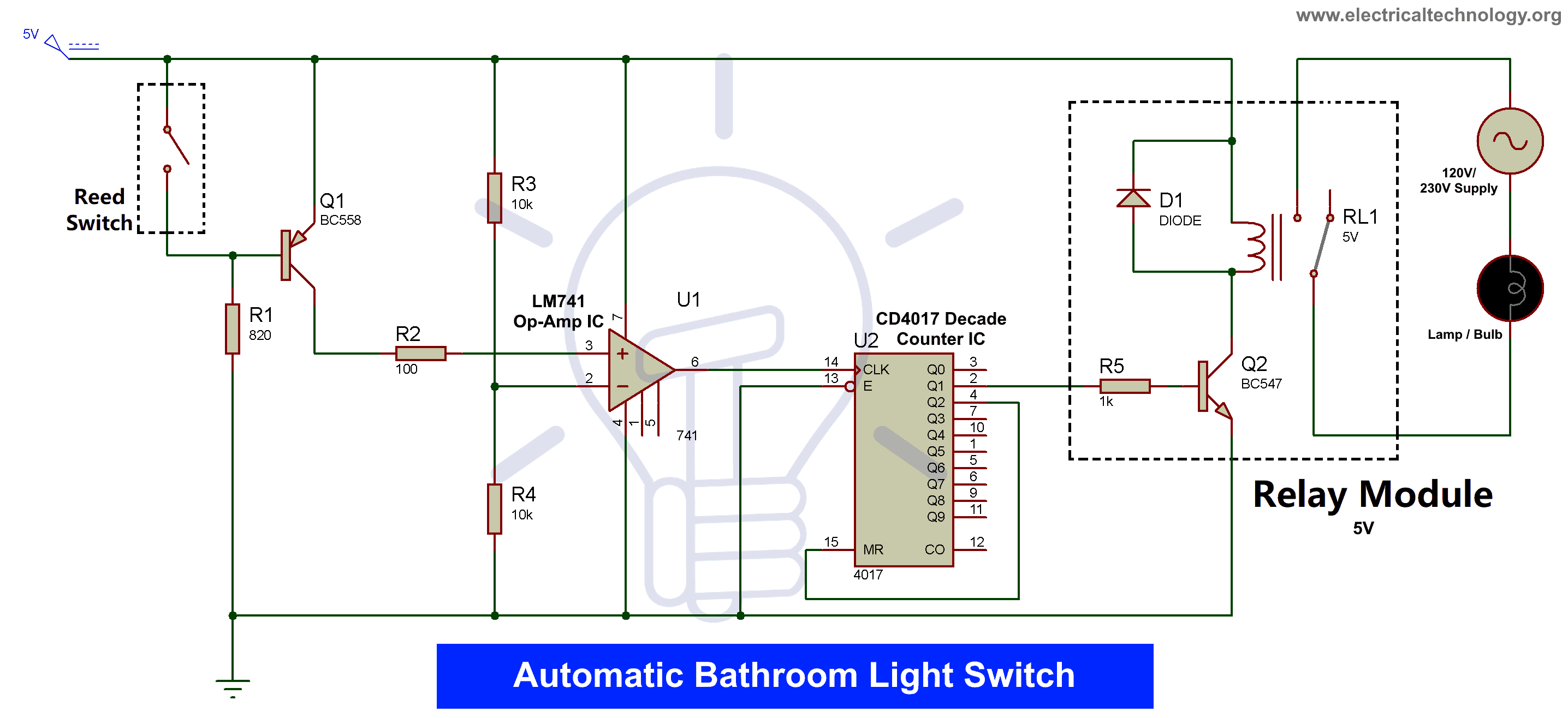
Automatic Bathroom Light Switch Circuit Diagram
The circuit diagram of this device consists of two main components: Operational Amplifier IC LM741 and Decade Counter IC CD4017. One end of the reed switch is connected to +5V power supply while the other is connected to the base of BC558 PNP transistor. The collector is connected to the +5 volts and the emitter is connected to the non-inverting input of the operational amplifier. The output pin of the LM741 connected to the clock pin of CD4017. Pin 2 is the output pin of the CD4017 which is connected to the input pin of the relay. Pin 4 of the CD4017 is connected to the RESET pin of the CD4017.
- Related Post: Smart Home Automation System – Circuit and Source Code
Before going further in the project I will let you know about the components we are going to use in the automatic light switch circuit project.
Reed Switch with Magnet
Reed switch is an electromagnetic switch which is used to control the flow of current in a circuit. In this project reed switch is used to detect the opening and closing of the gate. It contains a small magnetic sensitive switch subjected to small magnetic force which will either turn on or turn off the switch. The Reed switch is made up of two or more ferrous reeds. The switch is encased with a small glass tube-like envelope. The reeds becomes magnetized and move together or separate whenever a magnetic field is moved towards the switch..
There are two types of reed switches: Normally Open and Normally Closed. In the Normally closed switch initially do not touch each other and when made in contact with a magnet it pulls one reed to other and completes the circuit. The working of Normally Closed circuit is its opposite. Initially the two reeds are connected to each other and when a magnet is brought in contact with the reeds then two reeds gets separated away. This reed switch will be installed in the gate to detect the opening and closing of the switch.
LM741 Op-Amp IC
LM741 is an operational amplifier IC which is a DC-coupled high gain electronic voltage amplifier. It has only one operational amplifier which is used to compare two signals which are inverting and Non Inverting signal. Mostly operational amplifiers have higher DC gain therefore they can be used as voltage amplifier and to do mathematical operations in various circuits.
- Related Post: Automatic LED Emergency Light Circuit
Pinout of LM741:
| Pin No. | Name | Description |
| 1 | Offset Null | Used to set DC offset voltage |
| 2 | Input – | Inverting input signal |
| 3 | Input + | Non Inverting Signal |
| 4 | V- | Ground or Negative power supply |
| 5 | Offset Null | Used to set DC offset voltage |
| 6 | Output | Output of the operational amplifier |
| 7 | V+ | Positive power supply |
| 8 | NC | No connection |
This operational amplifier IC is used as a comparator IC in the mathematical circuits. If the voltage at Non-inverting input (+) is higher than the inverting input (-) then the output of the operational amplifier is HIGH. If the voltage at Non-inverting input (+) is lower than the inverting input (-) then the output of the operational amplifier is LOW.
LM741 IC has various applications in electric circuits like, comparator, DC amplifier, integrator, differentiator, summing amplifiers, Multivibrator, active filters and general feedback applications.
- Related Post: Automatic Night Lamp Using Arduino
CD4017 Decade Counter IC
The CD4017 is a CMOS Decade counter IC. CD4017 is used for low range counting applications. This IC is able to count from the zero to ten (the decade count). The supply voltage of this IC is between 3 to 15 volts and also it is compatible with transistor logic (TTL). The clock speed of CD4017 is 5 MHz,
Related Posts:
This IC is mainly used in counting applications and turn on 10 outputs sequentially in predefined time and reset the count whenever required. It indicates the status of the counting pin using Carry pin. This IC contains 10 output pins ranging from Q0 to Q9. The CD4017 IC works from 3 volts to 15 volts but generally it is powered at 5 volts at VDD pin and ground at Ground pin of the IC. The IC increments the counter from 0 to 9 (Q0 to Q9) each time in a sequence it senses a high pulse from the clock pin.
Related Posts:
This sequence can be interrupted by RESET and Clock Enable pins. By default both the pins are grounded, but if we make RESET pin HIGH then the counting again starts from zero, for instance if the count is at pin 5 and if we make HIGH RESET pin at this point then the counter comes at pin 0. If we make Clock Enable pin then the counting pauses at that point, for instance if we make HIGH the Clock Enable when the counter was at pin 5 then the counter pauses and stops at pin 5.
Pinout of CD4017 Counter:
| PIN No. | NAME | DESCRIPTION |
| 1 to 7 | Output pins | Output pins 5, 1, 0, 2, 6, 7 and 3 respectively |
| 8 | GND | Ground pin |
| 9 to 11 | Output pins | Output pins 8, 4 and 9 respectively |
| 12 | Carry-OUT | It completes one full cycle for every 10 clock cycles |
| 13 | Clock Enable | Enable pin enables the CD4017 IC |
| 14 | Clock | Clock signal is provided at this pin |
| 15 | Reset | Pin to reset the counter to 0 |
| 16 | VDD | 3 volts to 15 volts |
This CD4017 IC has many applications in Remote metering, automotive, medical electronics. This is mostly used as a counter in binary counter or binary decoder. This IC is also used in LED matrix, LED chaser and other LED projects.
BC558 PNP Transistor
BC558 is a PNP transistor in which the collector and emitter will be in the forward biased. When the base pin is held at ground and will be opened (Reverse biased) when a signal is provided to base pin. This is how a NPN transistor is different from a PNP transistor. It is used in switching and amplifier applications.
The gain of this PNP transistor is in the range of 110 to 800. The peak current that could flow through the Collector pin is 200mA, this combined with the high gain value which makes it an ideal choice for audio amplification applications. It is also used as a complement of transistors BC546 to BC550. A fixed DC voltage is required for the terminal to operate in the respective region of its characteristic curves. The transistor allows to flow current of 100mA across the emitter and the collector in fully biased condition. Hence, the region is named as the saturation region. The typical voltage allowed across the collector-emitter or base-emitter could be in the range of 200mV to 900mV. When the base of current of the transistor BC558 is removed the transistor becomes fully off, and we call that the transistor is in cut-off region.
- Related Post: Fully Automatic Water Level Controller using SRF04
Working of the Automatic Bathroom Light Switch Circuit
Connect the circuit as given in the circuit diagram properly. The reed switch is fixed while a magnet is fixed on the wall to change the state of the reed switch. This means that the reed switch will always remain in closed state when the door is closed and it will remain in the open state when the door is opened. So first you will open the door and then close it. Meanwhile the state of the reed switch will change two times, once while opening and second while closing the door. Opening of the door while result in making the operational amplifier to HIGH and then closing of door will make the operational amplifier to LOW state. This will change the state of counter to pin 2 which is further connected to the output of the relay and hence lights will glow on.
After completing your work in the washroom you will open the door and then you will close it. This will also change the operational amplifier flow HIGH to LOW. Hence it will change the counter state from pin 2 to pin 4. Pin 4 is connected to reset button which will take the counter to pin 0 which in result will turn off the relay and hence the light bulb. This is how the automatic light switch works.
In this way you can make a device like automatic on/off light switch which can automatically turn on and turn off the light of bathroom without the human intervention.
Related Electronic Projects:


Wiring
Hi
This is Balraj
I have a doubt
If i want the light on when door open then door close still light on
After finish work door open and close light goes off
How to connect for this
Use a T-FF in the toggle mode with a limit switch or magnetic contacts on the door wired to provide a clk pulse to the FF. This will invert lamp condition each time door opens and closes.
Delay….. Provide either use timer ic or controller
But my suggestion.. pir sensor is better option
Interesting and new ideas in the future.
Why would anyone want this in a bathroom? I go to a hospital that has this in the bathroom and right in the middle of going to the bathroom the light keeps going off i mean how much movement can you really do sitting on the toilet. Worst idea ever
Ive got something like that implemented in my home – bathroom – with an esp8266, pir, movement, light sensors, all reporting to a Raspberry Pi hub, using mqtt. Been working for the past 3 years without issues. Ive set a delay of 1m to turn off light if theres no movement. See here https://iot.piter.ro/my-first-device/
R.venkatesh
D.eee
PSR polytechnic College
Sivakasi
I don’t understand how this is any good. so you turn the light on and off by closing the door? It has no clue if it’s day or night or if someone is in the bathroom or not
There is no way to get the Led start blinking. It’s constantly lit on blue light. It’s not connected on any network since I replaced my wifi router. How can I reset it to make a fresh installation on a new router?
the circuit doesnot work. will you check your circuit diagram? you said + voltage across collector but the circuit shows + in emmiter. I have build as per the diagram but the circuit does not switch on the relay
Want to know in detail about the project automatic washroom light switch