How to Check Earthing and Measure Ground Resistance using a Multimeter?
Measuring ground resistance using a multimeter is generally not as accurate as using specialized ground resistance testers, but it can provide a rough estimate. Most multimeters are designed for measuring voltage, current, and resistance in low-power circuits. Here’s a basic guide on how to measure ground resistance and test the grounding system’s proper functionality using a multimeter:
Good to Know:
- According to NEC 250.56, the maximum grounding resistance is 25 ohms, and 50 ohms for sensitive applications. An additional ground rod needs to be installed if the ground resistance exceeds 50 ohms.
- According to IEC/BS EN 62561-2:2012, good earth resistance is 5 – 10 ohms.
- Recommended grounding resistance per IEEE and NFPA standards is typically < 5 ohms, also applicable to telecommunications.
It is recommended to use specialized equipment designed for accurate ground resistance measurements, such as a ground resistance tester or a clamp-on ground resistance meter. These instruments are specifically designed to provide reliable and accurate measurements in various grounding scenarios.
Testing the grounding system using a multimeter is an essential step to ensure the safety and effectiveness of electrical installations. Here’s a general guide on how to test the grounding system using a multimeter:
Note: Always follow proper safety precautions when working with electrical systems. If you are not familiar with electrical work, it’s advisable to consult with a qualified electrician.
Related Posts:
- How to Test Earthing – Grounding System using a Light Bulb?
- How to Measure Earth Loop Resistance Using Ammeter and Voltmeter?
Measuring the Grounding Resistor Using Multimeter
Materials Needed:
- Multimeter: Ensure that it’s capable of measuring resistance (ohms – Ω).
- Grounding Rod or Electrode: The grounding system typically involves a ground rod or electrode, which is a metal rod buried in the ground.
Steps to Measure the Grounding Resistance:
1. Set Up the Multimeter:
- Turn off power:
- Before connecting the multimeter, ensure that power to the system you are testing is disconnected to ensure safety.
- Select the ohm (Ω) setting: Set your multimeter to the ohm setting. This is typically indicated by the symbol “Ω.” Choose an appropriate range for the expected resistance values in the grounding system.
2. Check the Multimeter:
- Before connecting the multimeter to the grounding system, ensure that the multimeter is functioning properly by touching the probes together. The multimeter should show a very low resistance, as the probes are shorted.
- Identify the grounding system or electrode you want to measure. Clean the connection points to ensure good electrical contact.
3. Connect the Probes:
- Connect the black (COM – Negative) lead of the multimeter to a known good ground, such as a metal water pipe or a designated ground rod.
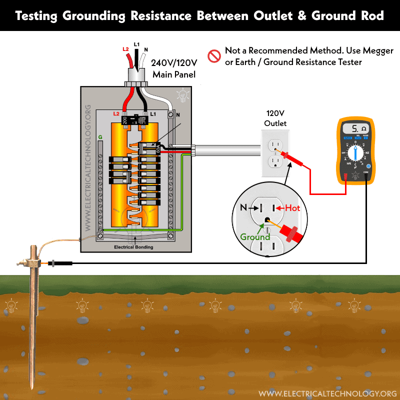
- Connect the Red (Positive) lead of the multimeter to the point in the grounding system you want to measure. This could be a ground rod, grounding electrode, other grounding connection like grounding port in an outlet. grounding terminal or metallic part (body) or chassis of a machine.

4. Measure Resistance:
- Observe the reading and record the resistance value displayed on the multimeter. The multimeter should display the resistance between the grounding rod and the known reference ground. A low resistance (ideally close to 0 ohms) indicates a good grounding connection.
5. Compare the Results:
Compare the measured resistance with any applicable standards, local area codes and guidelines. Ground resistance values can vary depending on the specific requirements of the system.
- Low resistance: If you get a low resistance reading, it means that there is a good connection between the grounding rod and the known ground. This is desirable for a proper grounding system.
- High resistance: If you get a high resistance reading, it indicates a poor grounding connection. This could be due to corrosion, loose connections, or other issues that need to be addressed.
Related Posts:
- How to Measure Ground Resistance? – Testing Earth Resistance
- How to Test the Earth Fault Loop Impedance – Various Methods
Testing the Grounding & Earthing System using a Multimeter
A digital or analog multimeter can be used to test and check if the earthing or grounding system is working properly. As it is a handy and DIY quick fix method, however, it’s important to note that this method may not be as effective. For higher accuracy, consider using a digital earth-ground resistance tester or a megger. If you’re still unsure, it’s advisable to contact a licensed electrician to perform the job in compliance with local area codes and regulations.
To verify the proper functioning of the grounding system using multimeter, follow these steps:
Testing the Ground System in 120V Circuit
Materials Needed:
- A Digital or analog Multimeter
- 120V or 240V / 230V Outlet / Receptacle / Socket
Steps to Test the Grounding System:
1. Set Up the Multimeter:
- Select the ACV Mode setting: Set your multimeter to the ACV (alternating current and voltage) setting. This is typically indicated by the symbol “~.” above the V. In analog multimeter, choose an appropriate range (250V in multimeter for 120V, 230V/240V testing circuit) for the expected resistance values in the grounding system.
2. Check the Multimeter:
- Before connecting the multimeter to the grounding system, ensure that the multimeter is functioning properly by touching the probes together while in resistance (ohm – Ω) mode . The multimeter should show a very low resistance or make a beep to show the short circuit, as the probes are shorted.
- Identify the desired outlet you want to make a test for grounding system. Clean the connection points to ensure good electrical contact.
3. Connect the Probes:
- Test 1:
- Connect the Black (COM – Negative) lead of the multimeter to the wider blade (Neutral) of ordinary 120V outlet.
- Connect the Red (+ Positive) lead of the multimeter to the narrow blade (Hot or Line) of the outlet.
- Observe the reading. The meter will display near to 120V. For example, Note the reading of 120V.

- Test 2:
- Connect the Red (+ Positive) lead of the multimeter to the narrow blade (Hot or Line) of the 120V outlet.
- Connect the Black (COM – Negative) lead of the multimeter to the ground port of the outlet.
- Observe the reading. The meter will display near to 120V. For example, Note the reading of 121V.

- Test 3:
- Connect the Black (COM – Negative) lead of the multimeter to the wider blade of 120V outlet.
- Connect the Red (+ Positive) lead of the multimeter to the ground port of the outlet.
- Observe the reading. The meter will display between 0 to 5V. For example, Note the reading of 0.5V.

Calculate the Leakage Voltage (Must be Less than 2V)
Leakage refers to the voltage moving from the ground/earth terminal to the neutral. If the leakage voltage exceeds 2V, the earthing – grounding system is likely faulty, and it is advisable to contact an electrician to configure it properly.
Based on the tested and recorded readings, calculate the total leakage on the outlet using the following formula:
(VPG – VPN) + VGN
Where:
- VPN = Voltage between Phase and Neutral
- VPG = Voltage between Phase and Ground
- VGN = Voltage between Ground and Neutral
Putting the values,
(121V – 120V) + 0.5V
= 1V + 0.5V = 1.5V
4. Compare the Results:
Compare the measured resistance with any applicable standards, local area codes and guidelines. Ground resistance values can vary depending on the specific requirements of the system. Based on the recorded values from above tests:
Good Grounding System:
- If the reading of tested voltage between Hot (Phase) and Neutral (say 120V) is almost equal to the tested voltage between Hot (Phase) and Ground port (say 121V).
- If the value of leakage voltage is less than 2V (based on calculated value as above).
Faulty Grounding System:
- If the reading of tested voltage between Hot (Phase) and Ground port is more than 1% e.g. 3V for 120V or 5V for 230V/240V.
- If the value of the leakage voltage is more than 2V (based on calculated value as above).
No Grounding System:
- If the reading of tested voltage between Hot (Phase) and Ground port is 0V. It shows there is no grounding system or the ground wire is broken somewhere in the middle.
Related Posts:
- How to Measure Resistivity of Earth Using Wenner Method?
- How to Test and Measure the Ground Resistance using a Megger?
Testing the Earthing System in 230V / 240V Circuits
Testing the earthing system for 230V or 240V is similar to the process outlined above for 120V. The following figures depict how to test the earthing system of a 230V British socket (BS1363). You can use the same method for testing a 240V outlet in the U.S.


Related Posts:
- How to Size the Earth Conductor, Earthing Lead & Earth Electrodes?
- Protective Multiple Earthing (PME) – TN-C-S – (MEN) and PNB
Tips and Precautions:
- Always turn off power before testing and take necessary safety precautions.
- Multimeter measurements may not be as accurate as those obtained with specialized ground resistance testers.
- The accuracy of the measurement can be influenced by the resistance of the leads and connections, as well as the condition of the grounding system.
- This method is more suitable for a quick check or as a preliminary assessment. For critical applications or when precise measurements are required, consider using dedicated ground resistance measurement equipment.
- If you get a high resistance reading, check for corrosion or loose connections and clean them.
- If possible, test at multiple points in the grounding system to ensure consistency.
- Periodically check the grounding system with proper maintenance to ensure ongoing effectiveness.
- If you’re unsure or uncomfortable with these procedures, it’s best to consult with a qualified electrician to ensure the safety and reliability of your electrical system and wiring installations.
- The author will not be liable for any losses, injuries, or damages resulting from the display or use of this information or any attempt to implement a circuit in the incorrect format. Therefore, exercise caution, as working with electricity poses inherent risks.
Related Tutorials on How to Use Digital and Analog Multimeters:
- How To Test Electrical & Electronics Components using a Multimeter?
- How to Test a Capacitor using Digital and Analog Multimeter? – 8 Methods
- How to Test a Diode using Digital & Analog Multimeter? – 4 Ways.
- How to Test a Transistor using Multimeter? – 4 Ways
- How To Perform a Continuity Test for Electrical Components with Multimeter?
- How to Measure Voltage using Digital and Analog Multimeter?
- How to Measure Current using Digital and Analog Multimeter?
- How to Measure Resistance using Digital & Analog Multimeter?
- How to Measure Power using Digital and Analog Multimeter?
- How to Measure Capacitance using a Multimeter?
- How to Measure Frequency using a Multimeter?
-
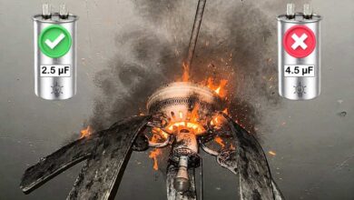 What Happens If You Install a Larger Capacitor in a Fan?
-
 Robotic Snakes that Crawl Power Lines to Detect Faults
-
 Motor Capacitor Calculator – Calculate Fan Capacitor Value
-
 Can You Install Breakers and Switches on Neutral Conductor
-
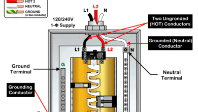 Difference Between Grounding, Grounded and Ungrounded Conductors
-
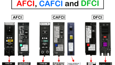 Difference Between AFCI, CAFCI, DFCI and GFCI?