How to Check Earthing and Measure Ground Resistance using Megger Earth Tester?
A Megger, or Megohmmeter (also known as Megger earth tester), is a specialized instrument commonly used for insulation resistance testing, but it can also be employed for measuring ground resistance and testing the earthing or grounding system to ensure that it is within acceptable limits and working properly. Meggers are particularly useful for assessing the integrity of electrical insulation and grounding systems. Here’s a step-by-step guide on how to measure ground resistance using a analog and digital Megger earth testers:
Good to Know:
- According to NEC 250.56, the maximum grounding resistance is 25 ohms, and 50 ohms for sensitive applications. An additional ground rod needs to be installed if the ground resistance exceeds 50 ohms.
- According to IEC/BS EN 62561-2:2012, good earth resistance is 5 – 10 ohms.
- Recommended grounding resistance per IEEE and NFPA standards is typically < 5 ohms, also applicable to telecommunications.
Note: Before proceeding, disconnect the earth lead / ground wire from the main distribution board / main panel when testing the ground resistance. Ensure that you are familiar with the specific model and features of your Megger earth tester, and follow the manufacturer’s instructions. Additionally, make sure to observe proper safety precautions, especially when working with electrical systems.
The author will not be liable for any losses, injuries, or damages resulting from the display or use of this information or any attempt to implement a circuit in the incorrect format. Therefore, exercise caution, as working with electricity poses inherent risks.
Testing & Measuring Ground Resistance using Digital Megger Earth Tester
- Select the Ground Resistance Measurement Function:
- Most Meggers have a specific function or setting for measuring ground resistance. Refer to the user manual for your Megger earth tester to identify the appropriate setting. In this tutorial, we have used Megger DET3TC – 3 terminals digital ground resistance tester.
- Prepare the Megger:
- Connect the leads of the Megger to the appropriate terminals on the instrument. There are typically two or three leads: one for injecting current into the ground (current electrode) and the other for measuring the voltage drop (potential electrode). The third one (Ground) is connected to the ground rod / earth electrode in the earth pit.
- Connect Ground Electrodes:
- Drive the ground electrodes into the ground at the desired measurement locations (see the user manual which states the recommended distance between the electrodes and spikes). These electrodes may include a current electrode (CE) for injecting current and potential electrodes (PE) for measuring voltage drop.
- Connect the current electrode (CE) to the Megger’s current terminal and the potential electrodes (PE) to the Megger’s potential terminal.
- Connect the Ground terminal to the ground electrode/rod already buried in the earth pit. (Make sure the the ground wire / earth lead is disconnected from the main panel / consumer unit when testing for earth / ground resistance).
- Set Measurement Parameters:
- Set the measurement parameters on the Megger, such as the duration of the test and the voltage applied. These parameters may vary depending on the specific model of the Megger. For example, set the 250-500V if you are going to test the 230V/240V wiring system.
- Perform the Test:
- Initiate the measurement by activating the Megger (by pressing the TEST button in digital Megger). The instrument will inject a known current into the ground and measure the resulting voltage drop.
- The Megger will calculate the ground resistance using Ohm’s law (), where is the ground resistance, is the voltage drop, and is the injected current.
- The Megger will display the ground/earth resistance in ohms on its digital display.
- Record and Analyze Results:
- Record the measured ground resistance values for each location.
- Compare the results with any applicable standards or local area codes and guidelines (refer to the NEC/IEC/NFPA & IEEE codes in the above Good to know section). Ground resistance values can vary depending on the specific requirements of the system.
- Interpret the Results:
- Analyze the results to determine the effectiveness of the grounding system. If the measured resistance is within the acceptable range, the grounding system is considered effective. If not, further investigation and improvement of the grounding system may be necessary.
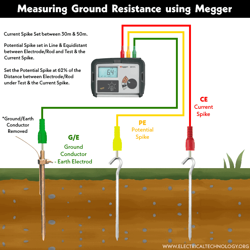
- The current spike should be set between 30 m and 50 m. For recommended distances, please refer to the user manual of the exact model of the earth tester.
- Potential spike set in line and equidistant between electrode/rod and test & the current spike.
- Set the potential spike at 62% of the distance between electrode/rod under test & the current spike.
Checking & Measuring Earth Resistance using Analog Earth Tester
The operation mechanism for testing and measuring earth or ground resistance using an analog earth tester is the same as above, except it requires some additional steps to match the results and obtain the appropriate value of earth resistance.
We are going to use the HIOKI FT3115 Analog Earth Tester. There are two dials in this earth tester: the deflection of the first one (on the left) always shows “0,” while the second one with a rotary knob (on the right) indicates the earth resistance. The lower knob is for selecting the value of resistances i.e. ×1Ω, ×10Ω, ×100Ω etc. The wiring setup to the earth tester terminals, electrodes, and spikes is the same as above. To determine the value of ground resistance;

- Set the resistance selection knob to the minimum value (e.g., ×1Ω and increase to ×10Ω if you didn’t get any result).
- Press the measurement button (or drive the rotating handle of DC generator in case of old models of analog Meggers).
- Rotate the rotary knob until the deflection point indicates “0” value. This represents the ground resistance value.
- For example, when rotary knob for reading is in between 9 and 10, and it matches the “0” on the deflection while the selected resistance knob at ×10Ω, it means the earth resistance is 9.5Ω.
- Compare the results with the local area codes. If they fall within the safe limit, it’s okay; otherwise, contact a licensed electrician to address the issue.
Testing and measuring ground resistance with a Megger provides a reliable and accurate assessment of the grounding system. Remember to consult the Megger earth tester’s user manual for specific instructions and guidelines tailored to your instrument model. Additionally, adhere to local electrical codes and regulations during testing procedures.
Related Posts:
- Electrical Earthing and Grounding – Methods, Types and Installation
- What is Ground Resistance Tester – Working of Ground or Earth Tester
- How to Measure Resistivity of Earth Using Wenner Method?
- How to Test Grounding / Earthing System using a Multimeter?
- How to Test Earthing – Grounding System using a Light Bulb?
- How to Size the Earth Conductor, Earthing Lead & Earth Electrodes?
- Protective Multiple Earthing (PME) – TN-C-S – (MEN) and PNB
- How to Measure Earth Loop Resistance Using Ammeter and Voltmeter?
- Design of Grounding / Earthing System in a Substation Grid
- Why are Salt and Charcoal Added in Earthing Pit for Grounding?
- What is the Purpose of Ground Wire in Overhead Transmission Lines?
- Difference Between Grounding, Earthing and Bonding
- What is the Difference Between Neutral, Ground and Earth?
- Difference Between Real Ground and Virtual Ground
- Why is the Grounding Wire Bare and Not Insulated?
- Why is Copper Rod Used as Ground Rod in Grounding / Earthing System?
-
 How to Wire Smart Scene Controller Switch
-
 How to Install a Home and Away Wireless Smart Switch
-
 Arkansas School Uses Rooftop Solar to Raise Teacher Pay
-
 How to Install a Wire-Free Smart Dimmer Anywhere Companion
-
 How to Wire a Smart Wireless Switch and Anywhere Companion
-
 Wiring a Smart Dimmer Switch Companion with a Digital Dimmer