Seven Segment Display: 7-Segment Display Types, Working & Applications
7-Segment Display: Seven-Segment Display Types, Working & Applications
In our daily life we come across many displays like television, smartphones, computers, traffic lights time counters, digital watches, washing machine, etc. We have different types of displays according to the use. You might have seen displays which are used to display waiting time on traffic lights or display used at railway stations for clocks, platforms and coaches. Those displays are called as seven segment displays.
What is Seven Segment Display?
A seven segment display (also written as 7-Segment Display) is an electronic display device which is used to display numerical characters from 0 to 9 or some special characters. There are seven LEDs present in one unit of the seven segment whose combination is used to make numeral or special characters according to the use. One or more such units are combined to display bigger numbers. This kind of display is generally used in digital clocks, calculators, wrist watches and many more electronic devices.
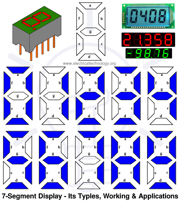
Following is the segment of 7-segment display.

In this tutorial we are going to learn about the seven segment display that how we can use it to display various numeral characters.
Construction of 7-Segment Display
There are seven small rectangular LEDs are present in a seven segment display and each led is called as segment. An additional led is also used in some displays for displaying decimal point to. Position of each led is set and named from A to G and this combination is used to display characters.
One pin from each led is brought out to give the signal to glow. The other pins of the LEDs are connected together to form a common pin. Led glows only when it is forward biased therefore if we make particular pin in forward bias mode we can make the characters of desired choice.
Related Posts:
- Binary Decoder – Construction, Types & Applications
- Binary Encoder – Construction, Types & Applications
Working of Seven Segment Display
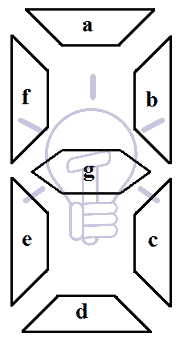
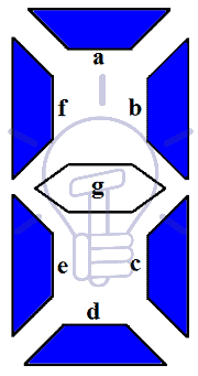
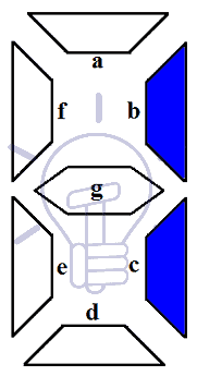
Seven LED segments of the display and their pins are “a”, “b”, “c”, “d”, “e”, “f” & “g” as shown in the figure given below. Each of the pins will illuminate the specific segment only.
We assume common cathode LED segment as our example. Suppose we want to display digit ‘0’, in order to display 0, we need to turn on “a”, “b”, “c”, “d”, “e”, “f” and turn-off the “g”. which would look like the figure given below.
It is working the same for other numbers like 0, 1, 2, 4, 5, 6, 7, 8 and 9 as shown in the above fig 1. The following section will show how the different types of seven segment display works with their circuit diagrams.
Related Posts:
Types of Seven Segment Display
An LED has two pins one cathode and one anode. Therefore there exists two types of seven segment displays:
- Common Cathode and
- Common Anode.
The difference in both types of seven segment is that: In common cathode all the cathode pins of seven LEDs is connected together whereas in common anode all the anode pins are connected together.
Let us learn more about the two types of seven segment display.
Common Cathode (CC) Seven Segment Display
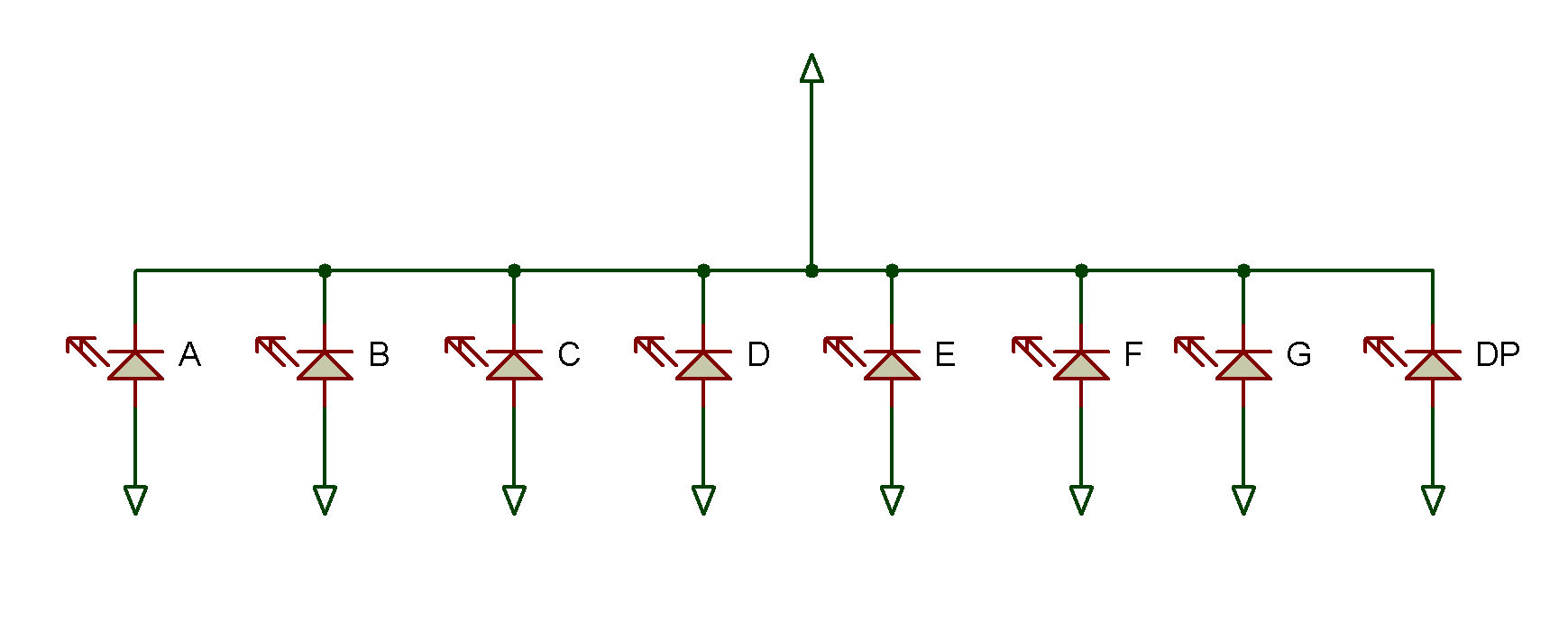
In common cathode display all the cathode pins are connected together to ground or logic 0. The other anode pin is taken out and are given high or logic 1 signal to illuminate the particular led segment from “a” to “g”. The diagram shown below is for the common cathode seven segment display.
Common Anode (CA) Seven Segment Display
In common anode display all the anode pins are connected together to high pin or logic 1. The other cathode pin is taken out and are given ground or logic 0 signal to illuminate the particular led segment from “a” to “g”. The diagram shown below is for the common anode seven segment display.

You cannot directly interchange common cathode and common anode segment units as in common cathode you have to illuminate particular segment by giving high signal at anode whereas ground signal to the cathode in common anode seven segment display unit, otherwise the LEDs will not glow. Common anode is more used as compared to common cathode as they sink more than source.
Here is the picture of the seven segment unit displays LEDs from “A” to “G” and one dot point as “DP”.
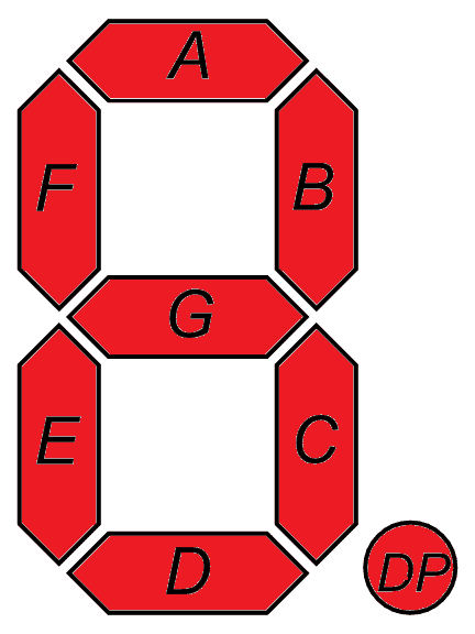
Now for instance if you wish to display “0” on the seven segment then you have illuminate LEDs A, B, C, D, E and F. Similarly if you wish to display “5” then you will illuminate LEDs A, F, G, C and D.
We can make a truth table which can help to denote number in binary or hexadecimal when connected to some microcontroller like Arduino UNO.
Related Posts:
- MUX – Digital Multiplexer | Types, Construction & Applications
- DEMUX – Demultiplexer | Types, Construction & Applications
| Numerals | A | B | C | D | E | F | G |
| 0 | 1 | 1 | 1 | 1 | 1 | 1 | 0 |
| 1 | 0 | 1 | 1 | 0 | 0 | 0 | 0 |
| 2 | 1 | 1 | 0 | 1 | 1 | 0 | 1 |
| 3 | 1 | 1 | 1 | 1 | 0 | 0 | 1 |
| 4 | 0 | 1 | 1 | 0 | 0 | 1 | 1 |
| 5 | 1 | 0 | 1 | 1 | 0 | 1 | 1 |
| 6 | 1 | 0 | 1 | 1 | 1 | 1 | 1 |
| 7 | 1 | 1 | 1 | 0 | 0 | 0 | 0 |
| 8 | 1 | 1 | 1 | 1 | 1 | 1 | 1 |
| 9 | 1 | 1 | 1 | 1 | 0 | 1 | 1 |
Protection of LEDs from High Currents
Sometimes high current damages the LEDs, therefore each led in the seven segment display needs to be protected from such high currents. The amount of light produced by the LEDs is proportional to the amount of forward current flowing in the LED.
If this forward current exceeds the limit then it can damage the led. So we need to control this forward current by using resistors to stop LEDs from getting damaged. Different colored LEDs have different forward voltage drop. For example forward voltage drop of blue led is 3.6 volts whereas it is 2 to 2.2 volts for red LEDs.
External resistors in series are connected with these LEDs to control the forward voltage drop. So if we want to connect resistor for LEDs segments of red light then the resistance can be calculated as below. If we have 5 volts DC battery, then the drop across led is 2 volts. Each led segment draws a current of approximately 15 mA to glow properly. Therefore the resistance is:
R = (5-2) / 0.015 = 200 ohms.
So the resistance should be approximately around 200 ohms.
In the circuit diagram shown, we have used a common cathode seven segment in which all the LEDs are connected to a resistor and then to a switch. Since it is a common cathode all the anode pins of LEDs are made common and other side cathode which is connected to resister is further given ground signals to turning on the switch. The respective led will glow on turning its switch on. From top to bottom there are 8 LEDs. LED at the bottom is for dot point and rest LEDs from top are A, B, C, D, E, F and G.
If you wish to display 1 on the seven segment display then you have turn on the switches B and C to provide ground to cathode. This way you will be able to display whatever you want without worrying about LEDs getting damaged.
To make things much easier we generally use an integrated circuit (IC) CMOS 4511 which is a seven segment decoder or driver. This seven segment display decoder is also known as Binary Coded Decimal (BCD) to seven segment display decoder and driver. Using this integrated circuit we do not have to worry about common cathode or common anode. There are many more integrated circuits available like TTL7447 which can handle one or more seven segment displays at a time.
Related Posts:
- Analog to Digital Converter (ADC) – Block Diagram, Factors & Applications
- Digital to Analog Converter (DAC) – Types, Working and Applications
CD4711 IC
CD4711 IC is a BCD to seven segment decoder driver integrated circuit. CD4711 is made from CMOS logic and the NPN transistor based output devices. It has properties of low power dissipation and high noise reduction and capable of giving 25 mA output current. It can take input voltage varying from 3 volts to 18 volts.
This IC is mainly used for driving various types of displays like seven segment and incandescent displays. It is 16 pin IC whose pinout is given below.
| Pin No. | Name | Description |
| 1, 2, 6 and 7 | B, C, D & A | Binary Coded Decimal Input to the IC |
| 3 | Lamp Test | Used to test the display |
| 4 | Blank Input | To turn off the all the LEDs of the display |
| 5 | Store | Stores a BCD input |
| 8 | GND | Ground |
| 9, 10, 11, 12, 13, 14 & 15 | E, D, C, B, A, G & F | Outputs which goes to 7 segment display |
| 16 | VCC | Power Supply (3 volts to 18 volts) |
The BCD to seven segment display decoder or driver takes 4 inputs and produces 7 outputs. The four side input is named as A, B, C and D. The decoder takes these four bits and convert them to 7 bits to produce the desired decimal digit to display on the seven segment. The output of driver integrated circuit is approximately equal to 25 mA of current to drive the led segment which makes it best for all colored LEDs. These ICs are commonly used to convert signals automatically that can be displayed on the seven segment.
In the circuit diagram shown below all the anodes are connected to seven output pins of the BCD decoder via resistors ranging between 390 ohms to 750 ohms. All the cathodes are connected together to the ground. Inputs of the decoder are connected to the switches which are connected to the VCC. VCC of the decoder is 9 volts.

Although led based seven segments are popular and used but nowadays led based seven segment displays are replaced by the liquid crystal displays due to more power consumption by led based displays as compared to liquid crystal displays.
Related Posts: