Electrical Grounding and Earthing – Methods, Types and Installation
Electrical Earthing & Grounding – Components, Methods & Types of Earthing – Electrical Grounding Installation According to NEC and IEC
What is Electrical Grounding or Earthing?
Earthing, also known as Grounding, is the process of connecting electrical systems, equipment, and devices to the ground (the Earth) to ensure safety and proper functionality in electrical installations. Earthing involves establishing a conductive path from the electrical system to the Earth’s conductive surface through grounding electrodes, conductive wires, and grounding conductors. In circuit schematics and wiring diagrams, it is represented by the ground symbol (⏚ or ⏋).
In other words, connecting the metallic (conductive) parts of an electric appliance or installation to the earth (ground) is known as Grounding or Earthing. The earthing or grounding system involves connecting the metallic components of electric machinery and devices to an earth plate (ground rod) or earth electrode via an earth lead (grounding conductor) buried in moist soil. This connection is established using a thick copper conductor wire with very low resistance for safety reasons.
Grounding, or earthing, is the process of connecting parts of electrical apparatus, such as metallic coverings and the earth terminals of socket cables, as well as stay wires that do not carry current, to the earth. Additionally, earthing involves connecting the neutral point of a power supply system to the earth to minimize the risk of danger during the discharge of electrical energy.
In the U.S., AC grounding involves connecting the metallic, exposed parts of a device to a ground rod through bonding, an equipment grounding conductor (EGC), and a grounding electrode conductor (GEC). Green or bare copper conductor is used for grounding in residential and commercial wiring installation. In the UK and countries following IEC standards, the practice is similar, but the terminology differs. The metallic frame of the device is connected to an earth plate via an earth continuity conductor. Green or green with yellow stripe is used for earthing in household wiring.
Difference between Earthing, Grounding, and Bonding
While the terms grounding and earthing are interchangeably used to represent the same thing, the term ‘Bonding,’ on the other hand, refers to the practice of joining two wires, conductors, pipes, or appliances together. It also encompasses connecting the metallic parts of different machines, not intended to carry electric current during normal machine operation, to ensure they are at the same electric potential. Let’s distinguish between the terms used as follows:
- Earthing:
In many parts of the world, especially in Europe, Commonwealth and IEC following countries, the term “earthing” is commonly used. Earthing refers to the process of connecting electrical systems and equipment to the ground (the Earth) to ensure safety and functionality. It involves creating a connection between the electrical system and the Earth’s conductive surface through grounding electrodes (such as ground rods or plates) and conductive wires. The primary purpose of earthing is to prevent electric shock, protect against electrical faults, and ensure the stable operation of electrical systems.
- Grounding:
In North America, particularly in the United States, the term “grounding” is often used. Grounding also refers to the same process as earthing but uses different terminology. It involves connecting electrical systems and equipment to the ground to achieve the same safety and operational objectives. Grounding includes establishing a connection to the Earth through grounding conductors, grounding electrodes, and grounding conductive paths.
- Earthing and Grounding:
Earthing and Grounding are essentially the same terms used to describe the process of establishing a connection to the ground. Grounding is the term commonly used for this purpose in North American standards, such as IEEE, NFPA, NEC, ANSI, and UL, while Earthing is the preferred term in European, Commonwealth countries, and British standards, like IS and IEC.
In essence, both earthing and grounding serve the same fundamental purposes in electrical systems.
- Bonding:
The term “Bonding” is used for joining two wires (as well as conductors, pipes, or appliances together). Bonding is known as connecting the metallic parts of different machines, which are not considered to be carrying electric current during normal operation, to bring them to the same level of electric potential.
In the context of the National Electrical Code (NEC), bonding refers to the practice of intentionally creating low-impedance connections between metallic components to ensure electrical continuity and conductivity.
Equipment Bonding Conductor (EBC) and the grounding and bonding of electrical systems, pools and spas, communications systems, and gas piping systems are addressed in NEC Article 250, which provides comprehensive guidelines. These guidelines include requirements for grounding electrode conductors, bonding jumpers, and grounding electrode systems.
Another example of bonding is connecting both the Neutral Bar and the Ground Bar in the main panel via a jumper wire. This connection is not required in the sub-panel, as it is already established in the main service load center.
Why is Earthing Important?
The primary purpose of earthing is to avoid or minimize the danger of electrocution, fire due to earth leakage of current through an undesired path, and to ensure that the potential of a current-carrying conductor does not rise with respect to the earth beyond its designed insulation.
When the metallic parts of electrical appliances (parts that can conduct or allow the passage of electric current) come in contact with a live wire, possibly due to installation failure or cable insulation breakdown, the metal becomes charged, accumulating static charge. If a person touches such charged metal, the result is a severe electric shock.
To prevent such instances, power supply systems and parts of appliances need to be earthed, transferring the charge directly to the earth. This is why Electrical Earthing or Grounding is essential in electrical installation systems.
Below are the basic needs of Earthing:
- To protect human lives and ensure the safety of electrical devices and appliances from leakage current.
- To maintain a constant voltage in the healthy phase, particularly in the event of a fault occurring on any one phase.
- To protect electric systems and buildings from lightning.
- To serve as a return conductor in electric traction systems and communication.
- To avoid the risk of fire in electrical installation systems.
Different Terms Used in Electrical Earthing
Earth / Ground: The proper connection between electrical installation systems via a conductor to the buried plate in the earth (earth plate or ground electrode) is known as Earth. The term Ground is used for the same thing in North America (NEC/CNC).
Earthed / Grounded: When an electrical device, appliance, or wiring system is connected to the earth through an earth electrode (ground Rod), it is known as an earthed device or simply “Earthed or Grounded”
Solidly Earthed: When an electric device, appliance, or electrical installation is connected to the earth electrode without a fuse, circuit breaker, or resistance/impedance, it is called “solidly earthed.”
Earth Plate / Ground Electrode: A conductor (such as copper ground rod or conductive earth plate) buried in the earth for the electrical earthing system is known as an Earth Electrode, Ground Electrode of Ground Rod. Earth electrodes come in different shapes such as conductive plates, conductive rods, metal water pipes, or any other conductor with low resistance.
Grounding Electrode Conductor (GEC) / Earthing Lead: The conductor wire or conductive strip connected between the Earth / Ground electrode and the electrical installation system and devices is knows as Grounding Electrode Conductor (GEC) in NEC and Earthing Lead in IEC/BS7671.
Equipment Grounding Conductor (GEC) / Earth Continuity Conductor: The conductor wire that is connected among different electrical devices and appliances, such as main panels, distribution boards, different plugs, and appliances, is known as equipment grounding conductor (EGC) in NEC and earth continuity conductor in IEC/BS7671. It may be in the shape of a metal pipe (fully or partially), or cable metallic sheath, or flexible wire.
EGC / Sub Main Earthing Conductor: A wire connected between the switchboard and distribution board, i.e., the conductor related to sub-main circuits. It is known as equipment grounding conductor (EGC) in North America.
Earth / Ground Resistance: This is the total resistance between the earth electrode and the earth in Ω (Ohms). Earth resistance is the algebraic sum of the resistances of the earth continuity conductor, earthing lead, earth electrode, and earth. The recommended values of ground resistance is given below in this article.
Points to be Earthed
Earthing is not done arbitrarily. According to NEC (National Electrical Codes) and IEEE (Institute of Electrical and Electronics Engineers) rules and regulations:
- All metal casings or metallic coverings containing or protecting any electric supply line or apparatus, such as GI pipes and conduits enclosing VIR or PVC cables, iron-clad switches, iron-clad distribution fuse boards, etc., should be earthed (connected to the earth).
- The earth pin of 3-pin lighting plugs/outlets, sockets, and 4-pin power plugs/sockets (as well as all other plugs/sockets and outlets/receptacles with a grounding pin) should be efficiently and permanently earthed.
- The frames of every generator, stationary motor, and metallic parts of all transformers used for controlling energy should be earthed by two separate and distinct connections with the earth.
- In a DC 3-wire system, the middle conductors should be earthed at the generating station.
- Stay wires for overhead lines should be connected to the earth by connecting at least one strand to the earth wires.
Components of Earthing / Grounding System
A complete electrical grounding / earthing system consists of the following basic components – Based on NEC and IEC/BS7671.
- Equipment Grounding Conductor – (EGC) / Earth Continuity Conductor
- Grounding Electrode Conductor (GEC) / Earthing Lead
- Ground Electrode or Ground Rod / Earth Electrode or Earth Plate
- Bonding Jumpers
Equipment Grounding Conductor (EGC) / Earth Continuity Conductor
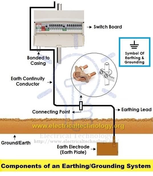
The part of the earthing system that interconnects all metallic components of an electrical installation (such as conduits, ducts, boxes, metallic switch enclosures, distribution boards/main panels, fuse holders, control/regulating devices, and metal parts of electrical equipment including motors, generators, transformers, and the metallic framework on which electrical devices are mounted) is known as the Equipment Grounding Conductor (EGC) in the NEC and the Earth Continuity Conductor in IEC terminology, as shown in the figure above.
The resistance of the earth continuity conductor must be very low. According to IEEE recommendations, the resistance between the consumer’s earth terminal and the EGC/earth continuity conductor (at the far end) should not exceed 1 Ω. In simple terms, the resistance of the earth wire should be less than 1 Ω.
The size of the EGC / Earth Continuity Conductor (or earth wire) depends on the size of the conductors used in the corresponding wiring circuit.
Size of EGC / Earth Continuity Conductor
The cross-sectional area of the circuit protective cable (CPC), also known as the protective conductor, should adhere to Regulations 543.1.3 and 543.1.4 (Regulation 542.3.1 when earth conductor is buried in the ground) and section of Section 544 – IEC Regulation 543.1.1 (Table 43.1 and Tables 54.2 to 54.6, as well as Table 54.7) in BS 7671:2018+A2:2022. The calculation based on reference formula from BS 7454 is also acceptable way to size the protective earth conductor.
The cross-sectional area of the Earth Continuity Conductor should be at least half of the cross-sectional area of the thickest wire used in the electrical wiring installation. The minimum size is 6mm2 and maximum wire size is 25mm2 – (Regulation 543, 544.1.1 of BS 7671 and based on IEC Table 5.1 (especially in case of PNB (Protective Neutral Bonding, also known as TN-C-S PNB) when PME earthing isn’t used)).
The size of PEN conductor and protective earth conductor (also known Circuit Protective Conductor (CPC) in PME Protective Multiple Earthing also known as TN-C-S PME) should be sized according to the Regulations 542.3.1 and Table 54.8 of BS 7671:2018+A2:2022.
According to NEC table 250.122, the minimum wire size for single equipment grounding conductor (EGC) is 4 AWG (21.15 mm2) copper (Section 392.10(B)(1)(c).
According to IEC, the typical size of the bare copper wire used as an earth continuity conductor is 3 SWG (32 mm2).
However, it’s important to note that you shouldn’t use a size less than 14SWG (2.9 mm2) for the earth wire. Copper strip can also be used as an earth continuity conductor instead of bare copper wire, but only if recommended by the manufacturer.
The recommended size of a grounding conductor in the National Electrical Code (NEC) depends on several factors, including the size of the circuit, the type of wiring, and the specific application. The NEC provides tables that specify the minimum size of grounding conductors based on the size of the circuit conductors and the type of raceway or cable used.
Equipment Ground Conductor (EGC) is sized based on NEC Article 250.122 & NEC Table 250.122. For example, in a typical residential wiring scenario, the NEC might specify the minimum size of the ground conductor based on the size of the circuit conductors. Common sizes for residential grounding conductors include #10 AWG or #8 AWG for smaller branch circuits.
For proper sizing the EGC or earth continuity conductor with solved examples and practical circuits, refer to the following step by step guide.
Grounding Electrode Conductor (GEC) / Earthing Lead or Earthing Joint
The conductor wire connected between the earth continuity conductor and the earth/ground electrode (such as a copper ground rod) or earth plate is called the earthing joint or ‘Earthing lead.’ The point where the earth continuity conductor and the earth electrode meet is known as the ‘connecting point,’ as shown in the figure above.
The earthing lead is the final part of the earthing system, which is connected to the earth electrode (located underground) through the earth connecting point.
It is advisable to minimize joints in the earthing lead, keeping them smaller in size and straight in direction.
Generally, copper wire can be used as the earthing lead, but copper strip is also employed for high installations as it can handle high fault currents due to its wider area compared to copper wire.
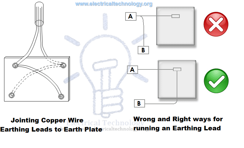
A hard-drawn bare copper wire is also used as an earthing lead. In this method, all earth conductors are connected to one or more common connecting points, and then the earthing lead is used to connect the earth electrode (earth plate) to the connecting point.
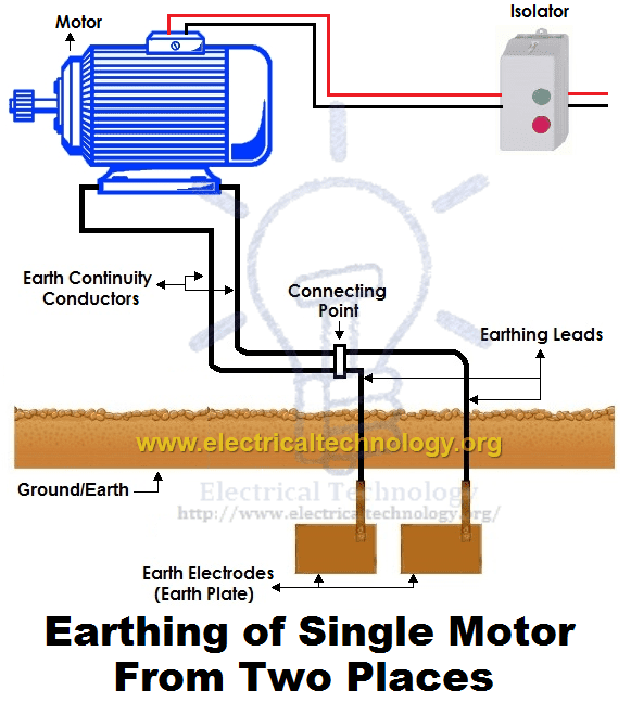
To enhance the safety factor of the installation, two copper wires are used as the earthing lead to connect the metallic body of the device to the earth electrode or earth plate. For instance, if two earth electrodes or earth plates are used, there would be four earthing leads. It’s important to note that the two earthing leads are not considered as parallel paths for fault currents but both paths should function properly to carry the fault current, ensuring better safety.
Size of the GEC / Earthing Lead
The size or area of the earthing lead should not be less than half of the thickest wire used in the installation.
The recommended size of the earthing lead is #4 AWG or #3 SWG as the largest and not less than #10 AWG or #14 SWG as the minimum. If a wire with dimensions of 37/.083 inches (0.20 inch2 or 129 mm2, nearest metric stranded size 120 mm2) is used, or if the load current is 200 Amps from the supply voltage, it is advisable to use copper strip instead of a double earthing lead. The earth lead connection methods are shown in the figure above.
Ground Electrode Conductor (GEC) is sized based on NEC Article 250.66 & NEC Table 250.66. For proper sizing the GEC or earthing lead with solved examples, refer to the following step by step guide.
Ground Electrode or Ground Rod / Earth Electrode or Earth Plate
A metallic electrode or plate buried in the earth (underground) serves as the final component of the electrical earthing / grounding system. In simple terms, the ultimate underground metallic plate, connected with the earthing lead, is referred to as an earth plate or earth electrode.
A metallic plate, pipe, or solid copper rod (as ground electrode) can be employed as an earth electrode, offering very low resistance and safely carrying fault current towards the ground (earth).
Size of Earth / Ground Electrode
Both copper and iron can be used as earthing electrode. The size of earth electrode:
- In case of copper
2×2 (two feet wide and two feet in length) with a thickness of 1/8 inch, i.e., 2′ × 2′ × 1/8″ (600 × 600 × 3 mm).
- In case of Iron
2′ × 2′ × ¼” = 600 × 600 × 6 mm
It is recommended to bury the earth electrode in moist soil. If this is not possible, then add water to the GI (Galvanized Iron) pipe to create the necessary moisture conditions. That’s why salt and charcoal are added in the earthing pit for grounding.
The size of ground rod
in case of solid copper:
- Height = 8 feet (≈2.5 meters)
- Diameter = ½ inches (12 mm)
In case of galvanized steel and hollow sections of GI:
- Height = 0.63 inches (16 mm)
- Diameter = ≈1 inch (25 mm)
In the earthing system, place the earth electrode in a vertical position underground, as shown in the figure above. Additionally, surround the earth plate (please note that the earth electrode and earth plate are the same) with a 1-foot (about 30 cm) layer of powdered charcoal and lime mixture. A ratio of 1:3 e.g. 1kg of Salt + 3 kg of charcoal) is good enough for general purpose plate earthing and grounding.
This practice facilitates a potential increase in the size of the earth electrode, ensuring better continuity in the earth (earthing system) and also helps maintain the moisture condition around the earth plate.
For proper sizing the ground rod and earth electrode / plate, refer to the following step by step guide.
- What is Ground Rod and How to Install a Ground Electrode in Grounding System?
- How to Size Earth Conductor, Earthing Lead and Earth Electrodes?
Avoid using coke (the remaining 88% carbon after burning coal in the furnace to emit all the gases and other components) or stone coal instead of charcoal (wood coal) because it can cause corrosion in the earth plate. Since the water level varies in different areas, the depth for earth electrode installation also differs. However, the depth for earth electrode installation should not be less than 10 feet (3 meters) and should be below 1 foot (304.8 mm) from the constant water level. Motors, generators, transformers, etc., should be connected to the earth electrode at two different places.
Ground Electrode or Earth Plate Size for Small Installation
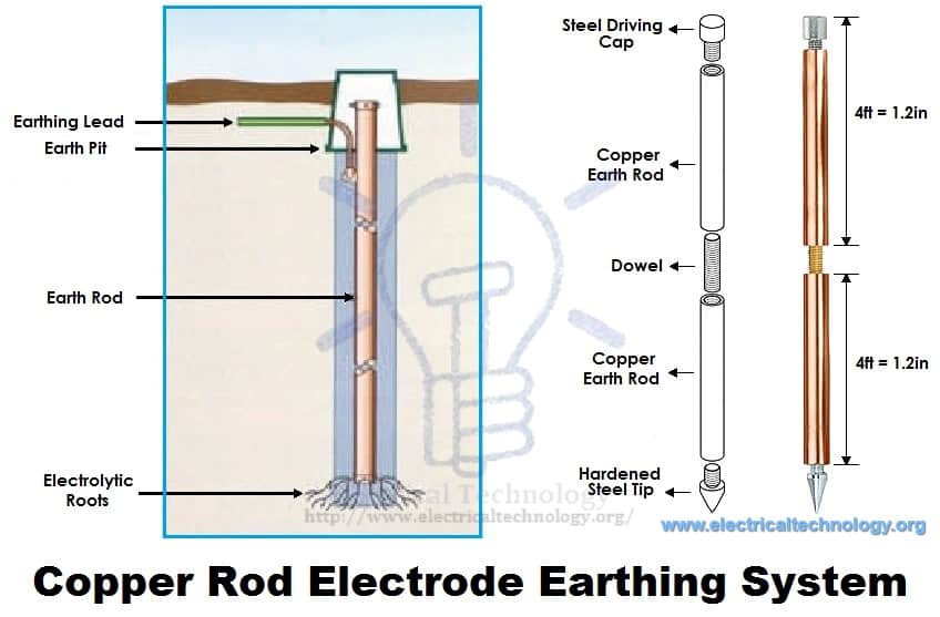
In small installations, use a metallic rod with a diameter of 25mm (1 inch) and a length of 2m (6ft) instead of an earth plate for the earthing system. The metallic pipe should be buried 2 meters below the surface of the ground. To maintain the moisture condition, surround the earth plate with a 25mm (1 inch) mixture of coal and lime.
For effectiveness and convenience, you may also use copper rods with diameters ranging from 12.5mm (0.5 inches) to 25mm (1 inch) and a length of 4m (12ft). The installation method with more details for rod earthing is explained below in this article.
Earth / Grounding Resistance
The ground resistance depends on multiple factors such as the length and depth of the ground electrode or plate, diameter of the ground rod, number of ground electrodes, type of grounding and earthing system, and the associated soil and environment.
Ground Resistance According to NEC
- According to NEC 250.56, the recommended grounding resistance should be less than 25 ohms, and for sensitive applications like ICU units in hospitals, a maximum resistance of 50 ohms is allowed. An additional ground rod should be installed if the impedance exceeds 50 Ω.
Ground Resistance According to IEEE and NFPA
- According to IEEE and NFPA standards, the recommended Ground resistance for earthing and bonding in telecommunications applications is typically less than 5 ohms.
Earth Resistance According to IEC
- According to the IEC, the ideal value of earth resistance should be between 1-10Ω. (See IEC/BS EN 62561-2:2012)
If ground resistance exceeds the recommended level, follow the steps below to address the issue:
- Perform soil treatment for conductivity according to IEEE 80-2013 (clause 14.5 (a), (b), (c), (d))
- Increase the diameter of the ground electrode
- Increase the number of grounding rods (using supplementary ground rods mention in 250.4(A)(5), 250.4(B)(4), and 250.54.)
- putting salt and charcoal in earth-pit to decrease the resistance to the suitable value.
Methods and Types of Electrical Earthing / Grounding
Grounding / Earthing can be achieved through various methods. The following discussion covers the different methods employed in earthing, whether in house wiring or in factories and other connected electrical equipment and machines.
NEC article 250 suggests different ways of grounding systems with eight types of grounding electrodes viz:
- Grounded Systems for <50V, 500 to 1,000V and >1,000V
- Ungrounded Systems
- Impedance Grounded Neutral Systems
- Direct Current (DC) Grounding
- Separately Derived Systems
- Grounding of Instrument and Meters/Relays
Similarly, there are five types of earthing systems in IEC and BS-7671 viz
- Terra-Neutral-Separate (TN-S): separate protective earth (PE) and neutral (N) conductors from the transformer to the consuming device
- TN-C-S: A type of earthing system that combines the neutral and protective functions in part of the system
- Terre-Terre (TT): The supply source and the load side is directly connected to the earth while the neutral and earthing conductors are separated during installation.
- Terminated Neutral Combined or “Terminated Neutral Combined Separate” (TN-C): The neutral and protective earth conductors are combined into a single conductor.
- Isolation Terre (IT): Where the the source is isolated from the ground or connected to it with a very high impedance.
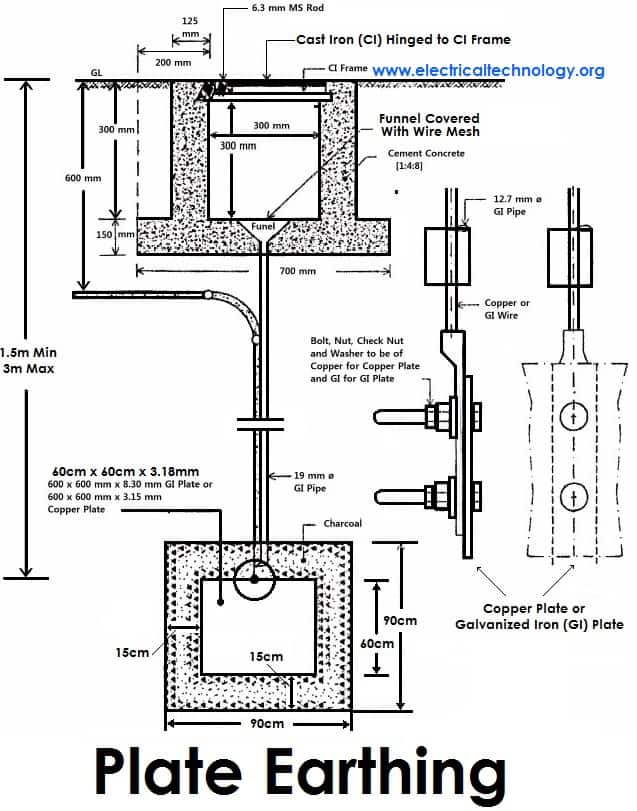
Plate Earthing:
In the plate earthing system, a plate made of either copper with dimensions 60cm × 60cm × 3.18mm (i.e., 2ft × 2ft × 1/8 in) or galvanized iron (GI) with dimensions 60cm × 60cm × 6.35 mm (2ft × 2ft × ¼ in) is vertically buried in the earth (earth pit), and it should not be less than 3m (10ft) from the ground level.
To ensure a proper earthing system, follow the steps mentioned in the Earth Plate introduction to maintain the moisture condition around the earth electrode or earth plate.
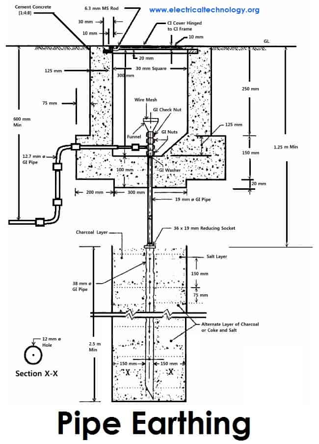
Pipe Earthing:
In this type of earthing system, a galvanized steel and a perforated pipe of approved length and diameter are placed vertically in wet soil. This is the most common earthing system.
The size of the pipe used depends on the magnitude of the current and the type of soil. The standard dimensions for the pipe are usually 40mm (1.5in) in diameter and 2.75m (9ft) in length for ordinary soil, or greater for dry and rocky soil. The moisture content of the soil determines the length of the pipe to be buried, but typically, it should be 4.75m (15.5ft).
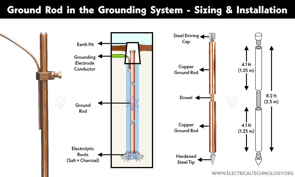
Rod Earthing
Grounding Rod or Ground Electrode earthing is the same method as pipe earthing. A copper rod with a diameter of 12.5mm (1/2 inch), or a galvanized steel rod with a diameter of 16mm (0.6in), or a hollow section of a 25mm (1inch) GI pipe with a length above 2.5m (8.2 ft) is buried upright in the earth either manually or with the help of a pneumatic hammer. The length of the embedded electrodes in the soil reduces earth resistance to a desired value.
A supplementary ground rod should be installed 6 feet (1.8 m) apart if the ground resistance exceeds 25 ohms (specified in NEC Section 250.56).
The exact sizes of the ground rod are mentioned in the above section of this article for “sizing the ground electrode”.
For more details and installation process of Ground Rod, see the article “What is Ground Rod and What does it Do? How to Install a Ground Electrode?“
Earthing through the Waterman
In this method of earthing, Galvanized GI pipes are utilized for earthing purposes. Ensure to check the resistance of GI pipes and use earthing clamps to minimize resistance for a proper earthing connection.
If a stranded conductor is used as an earth wire, clean the ends of the wire strands, and ensure they are straight and parallel before securely connecting them to the waterman pipe.
Strip or Wire Earthing:
In this method of earthing, strip electrodes with a cross-section not less than 25mm × 1.6mm (1in × 0.06in) are buried in horizontal trenches with a minimum depth of 0.5m. If copper with a cross-section of 25mm × 4mm (1in × 0.15in) is used, the dimension is 3.0mm2, whether it’s galvanized iron or steel.
If round conductors are used, their cross-sectional area should not be too small, for example, less than 6.0mm2 if it’s galvanized iron or steel. The length of the conductor buried in the ground should provide sufficient earth resistance, and this length should not be less than 15m.
General Method of Electrical Grounding / Earthing Installation
The standard step by step procedure for earthing electric equipment, devices, and appliances is as follows:
- Begin by digging a pit approximately 5 × 5 ft (1.5 × 1.5m) in size, with a depth of 20-30ft (6-9 meters) into the ground. (Note that the depth and width depend on the nature and structure of the ground.)
- Vertically bury an appropriate copper plate (usually 2’ × 2’ × 1/8” or 600×600×300 mm) in the pit.
- Attach 3/4 AWG/SWG earth leads (ground conductor) through nut bolts from two different places on the earth plate.
- Use two earth leads for each earth plate (in case of two earth plates) and tighten them securely.
- Apply grease around the joints to protect them from corrosion.
- Gather all the wires in a metallic pipe from the earth electrode(s), ensuring the pipe is 1ft (30cm) above the ground surface.
- To maintain moisture conditions around the earth plate, surround it with a 1ft (30cm) layer of powdered charcoal (powdered wood coal) and lime mixture.
- Use thimbles and nut bolts to tightly connect wires to the bed plates of machines. Each machine should be earthed from two different places, and the minimum distance between two earth electrodes should be 10 ft (3m).
- Ensure that the earth continuity conductor, connected to the body and metallic parts of all installations, is tightly connected to the earth lead. Perform a continuity test to verify continuity.
- Lastly, test the overall earthing system with an earth tester. If everything aligns with the plan, fill the pit with soil. The maximum allowable resistance for earthing is 1Ω. If it exceeds 1 ohm, increase the size (not length) of earth lead and earth continuity conductors. Keep the external ends of the pipes open and periodically add water to maintain the moisture condition around the earth electrode, crucial for a better earthing system.
NEC Specifications of Grounding
The National Electrical Code (NEC) provides specifications for grounding in various sections. Here are some key sections related to grounding in the NEC:
- NEC Article 250 – Grounding and Bonding:
- 250.4 – Grounding Path and Connections: Specifies that the path to ground from circuits, equipment, and grounding electrodes should be permanent and continuous.
- 250.50 – Grounding Electrode System Installation: Provides requirements for the installation of grounding electrode systems, including the types of electrodes and their installation methods.
- 250.52 – Grounding Electrodes: Describes the types of grounding electrodes and their installation requirements.
- NEC Article 250 – Grounding and Bonding (Part II):
- 250.70 – Grounding Conductor Sizing: Specifies the sizing of grounding conductors based on the size of the circuit conductors.
- 250.122 – Size of Equipment Grounding Conductors: Provides the minimum size requirements for equipment grounding conductors.
- NEC Article 250 – Grounding and Bonding (Part III):
- 250.130 – Equipment Grounding Conductor Installation: Outlines the methods and requirements for installing equipment grounding conductors.
- 250.136 – Equipment Grounding Conductor Material: Specifies the materials that can be used for equipment grounding conductors.
- NEC Article 250 – Grounding and Bonding (Part V):
- 250.164 – Protection of Grounding Conductors: Provides requirements for protecting grounding conductors against physical damage.
- NEC Article 250 – Grounding and Bonding (Part VII):
- 250.210 – Grounding of Equipment: Outlines the requirements for grounding non-current-carrying metal parts of equipment.
SI Specification for Earthing
Various specifications regarding earthing, as recommended by Indian Standards, are provided below:
- An earthing electrode should be positioned (installed) at a distance of at least 1.5m away from the building whose installation system is being earthed.
- The earth resistance should be low enough to enable sufficient current flow to operate protective relays or blow fuses. Its value is not constant as it varies with weather due to dependence on moisture (but should not be less than 1 Ohm).
- The earth wire and earth electrode should be made of the same material.
- The earthing electrode should always be placed in a vertical position inside the earth or pit to be in contact with all the different earth layers.
Dangers of Not Earthing a Supply System
As emphasized earlier, earthing is provided for several crucial reasons:
- To avoid electric shock:
- This is a primary purpose of earthing. By connecting the electrical system to the ground, the risk of electric shock is significantly reduced.
- To avoid the risk of fire:
- Earth leakage current, if not properly grounded, can follow unintended paths and lead to the risk of fire. Proper earthing helps direct such currents safely to the ground.
- To ensure that no current-carrying conductor rises to a potential with respect to the general mass of earth beyond its designed insulation:
- Maintaining the designed insulation of conductors is critical. Earthing prevents conductors from reaching potentials that could compromise their insulation and safety.
However, if excessive current is not earthed, appliances may be damaged without the protection of a fuse. It is important to note that excessive currents are grounded at generating stations, minimizing the current carried by earth wires. Therefore, it may not be necessary to earth individual wires (live, earth, and neutral) contained in a PVC. Earthing the live wire can have catastrophic consequences.
I witnessed a tragic incident where a person lost their life due to a live wire getting cut from an overhead pole and falling to the wet ground. Excessive current is typically grounded at generating stations, and if there is a fault in the earthing system, earth fault interrupters provide additional protection. Fuses play a role when the power transmitted exceeds the rating of our appliances, preventing the current from reaching the appliances and safeguarding them by blowing off in the process.
In electrical appliances, if excessive currents are not earthed, users may experience severe shocks. Earthing in appliances becomes active only when there is a problem, serving as a safety measure. In the event of a fault, such as direct contact between a live wire and a metallic part of an electrical appliance, the metal becomes charged, accumulating static charge. Earthing ensures that this charge is transferred to the ground, protecting users from potential shocks.
Moreover, if a live wire accidentally touches the metallic part of a machine in a faulty system, and an individual touches that metallic part, the current flows through their body to the ground, leading to electric shock or even serious injuries and death. This underscores the critical importance of proper earthing practices.
Premium Resources about Electrical Grounding & Earthing – NEC & IEC
- How to Size Equipment Grounding Conductor (EGC)?
- How to Size Grounding Electrode Conductor (GEC)?
- How to Size Earth Conductor, Earthing Lead & Earth Electrodes?
- How to Measure Ground Resistance? Testing Earth Resistance
- How to Measure Earth Loop Resistance Using Ammeter and Voltmeter?
- How to Measure Resistivity of Earth Using Wenner Method?
- How to Test the Earth Fault Loop Impedance – Various Methods
- How to Test Grounding / Earthing System using a Multimeter?
- How to Test Earthing & Grounding System using a Light Bulb?
- Why Doesn’t DC System Require a Grounding System Similar to AC System?
- Why is Copper Rod Used as Ground Rod in Grounding / Earthing System?
- Why is the Grounding Wire Bare and Not Insulated?
- Why is the Ground Wire Size Smaller than the Hot Wire?
- Why is the Ground Wire Always Positioned Above the Overhead Power Lines?
- Why Must Neutral and Ground Wires Be Bonded in the Main Panel?
- Why are Neutral and Ground Wires Separated in a Subpanel?
- Why is the Grounding Wire Bare and Not Insulated?
- Why Earth Pin is Thicker and Longer in a 3-Pin Plug?
- Why are Salt and Charcoal Added in Earthing Pit for Grounding?
- What is the purpose of Earth or Ground wire in overhead Transmission Lines
- What is Ground Rod and How to Install a Ground Electrode in Grounding System?
- How Do Grounding and Earthing Shoes Work to Prevent ESD?
- How Does the Grounding System Work in Aircraft & Submarines?
- Should You Connect GND and 0VDC? Combined AC & DC Grounding
- Can you Combine AC and DC Ground in a Solar Installation?
- Will I Get an Electric Shock If I Touch the Ground Wire?
- Design of Grounding / Earthing System in a Substation Grid
- Grounding and Methods of Earthing in PV Solar System
- Ground Terminal Up or Down: Which Way Should Outlets Face?
- Protective Multiple Earthing (PME) – TN-C-S – (MEN) and PNB
- What is Ground Resistance Tester – Working of Ground or Earth Tester
- Difference Between Neutral, Ground and Earth
- Difference Between Grounding, Earthing and Bonding
- Difference Between AC Ground and DC Ground?
- Difference between Real Ground and Virtual Ground?
- Difference Between EGC and GEC in Electrical Grounding


Very informative article.
Thanks for share great info with us. I will recommend you to prefer plate earthing than pipe earthing. Plate earthing is the best earthing.
Why plate earthing is the best earthing…
very useful guidance for earthing thanks
Very helpful
” To avoid such instances, the power supply systems and parts of appliances have to be earthed so as to transfer the charge directly to the earth ”
Not to transfer energy to earth but to ” short circuit live to earth together to operate the over current device to disconnect live wire instantly..so protect person or equipment.
Outstanding blog, covering almost everything about the types of earthing! The importance of earthing, its types and fuse is very well explained. Thanks. Hope to see such informative blogs more.
Thank for appreciation…. :)
this is wonderful
such a phaburus guide, engineers read about it pliz!! me am always thea and have gained more.
Is it ever under any circumstances dangerous to touch an earthed line?
Also for grounding electrical components, does it make any difference on the type of metal used in the grounding wire?
Respected Sir,
In the existing theory of electrical earthing the fate of electrons after it reaches the earth through earthing/ground rod remain unidentified.
We have shown that the electrons after reaching the earth/ground through the grounding rods are actually transported to the source through orientations of water molecules. Kindly see the links and post your valuable suggestion:
1) “The Phenomenon of Electrical Earthing Explained”
http://hpathy.com/scientific-research/phenomenon-electrical-earthing-explained-orientations-water-molecules/
2) “Delocalization of hydrated electron conducts………”
http://hpathy.com/scientific-research/delocalization-of-hydrated-electrons-conduct-electrical-energy-in-water-or-aqueous-solutions/
Thanking you.
Biplab Chakraborty
Amazing articles. Deep insights!
Request if you can exclusively mention a pipe earthing for residential use for current ranging from 20 to 40 Amps.
A schematic diagram labelling dimensions, parts, quantity of charcoal, lime and salt.
Can we get effective earthing of 8 feet digging out of 4 to 6 feet digging by adopting any suitable means.
Thanks
Thank you for your tutorials. It is very useful for me. We are going to change an electricity at our house and also make new powerful grounding. We have already bought Dehn equipment for it and wanted to ask a master to help us. But with your tips I’m sure that I can do everything by myself! Thanks again!
IS ALUMINIUM AS EARTH STRIP OK FOR EARTHING
Hello, We are currently using a single earthing for our single phase Electricity connection.But we are not planning to go for 3 phase connection.The guys who are going to install a 3 phase told that we need a double earthing for 3 Phase connection.So do we need to install a new earthing for 3 phase connection?
I got. Problem i checked and found 12 v in btwn nutral or earth wire is that right ??? Either not so how much volt seen in btwn that
It must be within 6volt
thanks it is very helpful i got much from it .
Exelent explanations and diagrammd
I have a doubt on providing the coal and lime around the rod or plate
earthing grout plate for human body
Thanks for the lecture, is a good indeed,you just upgraded my knowledge, thanks for the good good work,keep it up.
Can I have the tutorial on inverter connection diagram, and battery connection sent to my box.
very nice explanation
the contents given above are very informative and useful for a common person interested with electrical installation and safety point of view. please clear for a residential building, how much distance should be kept apart from an earth pit with safety point of view.
thanks it elaborates and teaches much about it
Engineering Experts,
I have a question regarding the Earth Continuity Conductor Sizing for a residential house.
As you said here “The cross sectional area of the Earth Continuity Conductor should not be less than the half of the cross sectional area of the thickest wire used in the electrical wiring installation.”
Per this, would the below statements be a safe design consideration for a residential house with 3 Ph Supply & load of 6kW with 40A main Isolator & ELCB.
1. For 2 Ton AC Circuit & Load of 8 Amps. 4 mm flexible wire used for Phase & Neutral.
Earthing Wire used is 2.5 mm
2. For Power Socket with upto 1500W load. 2.5 mm wire used for Phase & neutral.
Earthing Wire used is 1.5 mm
3. For other circuits: 1.5 mm wire used for Phase & Neutral.
Earthing Wire used is 1.5 mm
Kindly help me with the earthing continuity conductor sizing query. thanks.
how much distance between installation and earthing
very much usefull
very accurate information
THANKS for your information it has been very educative and useful .
Very useful information,
however, may be the values of earthing requirement for different equipment, areas or locations to be mentioned. like for lightning protection how much allowable limit for earthing resistance of pit is required.
Thank for the valuable information, the concept of earthing is clear to me now.
Very clear and precise article.I’d love to get more of such articles.kudos
I have never heard of Earthing before. I didn’t know that it was the process of connecting metallic parts of an electrical appliance to the ground. It sounds like it would be very helpful in helping to keep the dangers of electrocution to a minimum. If the electricity has somewhere to go into the ground quicker it will go there instead of somewhere else. That’s really cool! I never knew that was the purpose of Earthing. Thanks for the information!
100 kv industrial connection design for erthing
i was looking for the types of earthing #only. but surprisingly I got more than what I wanted.
thanks alot.
I really recommend your article to all electricians.
Excellent chapter for electrical person, many thanks for the one who took the initiative step to up load this chapter, will be helpful if you upload about insulation resistance testing and electrical containment example tray trunking and G I Conduting and conduit bending
Thank you very much for this information.
Can you please learn us how we design electrical earth mesh?
Thanks for your comment about how you should hire an electrician to help you with earthing, where appliances are installed into the ground. I like how you said that this is an important safety precaution made to a power supply. If someone was considering in earthing, other mining equipment or electrical work, I would assume that they would keep your post in mind.
I really gained alot with your post.Thanks
Thank for the valuable information, very informative article
it helps me very much thanking you so much
Very helpful ..for every one…God bless you ..
what is new method of earthing
this is superb I have no words to express my joy to assorted my self with you I have lean a lot in earthing works and installations thanks
What is the dimensions are to be for earthing rod that is connected to pipe for eliminating static electricity from grinding?
In our Housing Society Complex in Pune, India, the earthing system has gone dry over past 10 years with NIL maintenance. We wish to install a proper pipe type earthing system preferably with NIL maintenance necessary for a long term for all the electric meters of the residents (112 flats presently). Can you arrange for a visit, assessment and quotation for the job ?
In dry soil, use an Ufer ground.
https://www.ecmag.com/section/codes-standards/what-ufer-ground-concrete-encased-grounding-electrodes
This is concrete encased re-bar which is bonded together.
thanks find helpful
what are other reasons for earthing a building/industriy
These are the reasons why:
– Safety of Occupants
– Protection of Electrical Equipment
– Lightning Protection
– Compliance with Electrical Codes and Standards
– Reduction of Electromagnetic Interference (EMI)
– Fire Safety
– Continuous Power Supply
– Mitigation of Voltage Fluctuations
– Protection Against Stray Currents
– Facilitation of Fault Detection
– Insurance Requirements
good presentation
Thanks for sharing.
Those who can seize the opportunity to walk in front of them will succeed in all likelihood
I noticed this:
“The earth resistance should be low enough to cause the flow of current sufficient to operate the protective relays or blow fuses. It’s value is not constant as it varies with weather because it depends on moisture (but should not be less than 1 Ohm).”
I think this is backwards. It should not be MORE than 1 ohm, instead of less.
Dear, we have an ongoing project for power house, and we are instantiating MV gensets in the main power plant. There is an existing earthing system with old drawings, This system needs to be tested and rectified if necessary. Please advise if you are capable to make new design. required also to provide below inquiry: Potential rose calculation Step voltage calculation Touch voltage calculation please let me know if you are able to do that, to share with you all of component drawing and details.
Very Useful Content Sir .
thanks a lot for helpful information
How to earth the surge arrester and neutral of the lv of a dtranfmr?
such a wonderful article very helpful on earthing & grounding.
hello, just a clarification for everyone, a current leaving the source will always go back to its source. and earth is the the source of electrical current but its the transformers from utility distribution. neutral and ground must be bonded on the first disconnecting means(1st electrical panel). without bonding neutral and ground, the current will not have a return path back to its source(transformers) in case there is ground fault, and this is very dangerous and no way to trip the breakers and when someone touches an energize metallic casing he/she will get severe shocked. always remember, current will not only travel to ground or least resistance but to any available path.
You have explained plate earthing and pipe earthing in a very easy manner. You have written very detailed content. You also share the data and images which is actually adding a value in this content. You have done a good job in this article.
Which circuit breaker should be used for grounding and earthing applications?
There is a lot of talk about grounding for electric needs. What about sheets, pads, mats for personal grounding? We no longer walk barefoot or sleep on the ground. What can you tell me practical information on this perspective? Not even sure what I need to know in order to make a purchase of all the available products out there.