What is Ground Rod and How to Install a Ground Electrode in Grounding System?
Ground Rod in Grounding System – Size, Role, Types, Installation and Applications
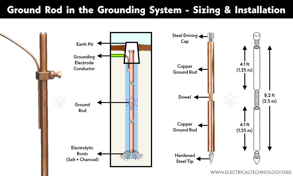
What is a Ground Rod?
A ground rod, also known as an earthing rod, grounding rod or ground electrode, is a long, slender metal rod that is typically made of materials like copper or steel. It is buried in the ground and electrically bonded to the main service panel. The primary purpose of the ground rod is to provide an electrical connection between an electrical system and the Earth’s ground, ensuring safety and proper functioning of the system.
Materials
A grounding rod made of pure and solid copper in the form of a copper rod is the preferred choice for grounding and earthing systems. Other materials such as aluminum, zinc, stainless steel, or copper-clad or copper-coated galvanized steel are also commonly used for grounding rods and earthing plates based on the system requirements in earthing and grounding systems.
Related Posts:
- Why is the Grounding Wire Bare and Not Insulated?
- Why is Copper Rod Used as Ground Rod in Grounding / Earthing System?
Length and Width
The minimum length of a copper rod is 8 feet (approximately 2.5 meters), with a diameter of ½ inches (12 mm). For galvanized steel and hollow sections of GI (Galvanized Iron) pipes, suitable sizes are 0.63 inches (16 mm) and ≈1 inch (25 mm) respectively.
Grounding Resistance
The grounding resistance is affected by the length/depth of the ground electrode, diameter of the ground electrode, number of ground electrodes, and ground system design.
According to NEC 250.56, the recommended grounding resistance should be less than 25 ohms, and for sensitive applications like ICU units in hospitals, a maximum resistance of 50 ohms is allowed. An additional ground rod should be installed if the impedance exceeds 50 Ω.
According to IEEE and NFPA standards, the recommended grounding resistance is typically less than 5 ohms, and this requirement also applies to grounding and bonding in telecommunications applications.
According to IEC (IEC/BS EN 62561-2:2012) the good ground resistance is between 5 – 10 ohms.
If the resistance is higher than the recommended value, perform soil treatment for conductivity according to IEEE 80-2013 (clause 14.5 (a), (b), (c), (d)) standard to reduce the resistance of the grounding system. Alternatively, you may increase the diameter of the ground electrode, increase the number of grounding rods (using supplementary ground rods) and putting salt and charcoal in earth-pit to address the higher resistance.
The Role of a Ground Rod in a Grounding System
Ground rods are typically installed at a depth below the Earth’s surface, which can vary depending on local electrical codes and requirements. The rod’s connection to the electrical system is made using conductors and grounding clamps. Proper grounding is crucial for safety and to ensure the effective operation of electrical and electronic equipment, as it helps prevent electrical hazards and disturbances. Ground rods are commonly used in various applications as follows:
Protection in Electrical Systems
In electrical wiring, ground rods are used to establish a grounding system. The rod is driven into the ground and connected to the grounding conductor of an electrical circuit or the ground terminal of electrical equipment. This helps to safely dissipate electrical faults, lightning strikes, and static electricity into the Earth, preventing electrical shock hazards and equipment damage.
Lightning Protection
Ground rods are a key component of lightning protection systems. Lightning rods and conductors are connected to ground rods to provide a path for lightning strikes to safely dissipate into the ground, reducing the risk of fire or structural damage.
Telecommunications
Ground rods are used in telecommunications systems to provide a common ground reference for various equipment and protect against voltage surges and electromagnetic interference.
Industrial and Scientific Applications
Grounding systems are essential in industrial settings and scientific laboratories to maintain safety and proper operation of equipment, particularly in situations where sensitive electronics or volatile materials are involved.
Types of Grounding Rods
- Solid copper ground rods
- Copper-clad galvanized steel
- Copper-coated galvanized steel
- Copper-bonded ground rods
- Stainless steel ground rods
- Galvanized steel ground rods
Solid Copper Ground Rods
Solid copper ground rods are preferred for their excellent electrical conductivity and corrosion resistance. They are used in grounding systems to establish a reliable connection with the earth for electrical safety and effective fault current dissipation.
- Life expectancy = 20 to 40 years
Copper-Clad Galvanized Steel Ground Rods
These rods combine the strength of galvanized steel with the conductivity of copper. The a small layer of copper cladding enhances their performance in grounding systems, offering a cost-effective alternative to solid copper rods.
- Life expectancy = 10-15 years
Copper-Coated Galvanized Steel Ground Rods
Similar to copper-clad steel, copper-coated galvanized steel rods are engineered for durability and conductivity. The copper coating ensures reliable performance in various grounding applications.
- Life expectancy = Up to 40 years
Copper-Bonded Ground Rods
Copper-bonded ground rods feature a thick layer of copper bonded to a steel core. This design provides both strength and electrical conductivity, making them suitable for grounding systems that require a balance of these characteristics.
- Life expectancy = More than 40 years
Galvanized Steel Ground Rods
Galvanized steel ground rods provide a cost-effective option for grounding systems. While they may not be as conductive as copper-based alternatives, they are commonly used in various electrical and industrial applications to establish reliable ground connections.
- Life expectancy = 10 – 15 years
Stainless Steel Ground Rods
Stainless steel ground rods offer excellent corrosion resistance, making them suitable for harsh environments and applications that demand long-lasting grounding solutions. They are often chosen for their durability and low maintenance.
- Life expectancy = up to 50 years
How to Install a Ground Rod?
Installing a ground rod is an important part of establishing an effective grounding system. Here are general steps for how to install a ground rod:
Materials and Tools You’ll Need:
- Ground rod
- Ground rod clamp
- Hammer or rotary hammer drill with a ground rod driver bit
- Safety gear (gloves and safety glasses)
Installation Steps:
- Select the Location: Choose a suitable location for installing the ground rod. It should be near the electrical or electronic equipment (such as main panel or specific machine) that requires grounding. Ensure there are no underground utilities, pipes, or obstacles in the path of the ground rod.
- Drive the Ground Rod: Use a hammer or a rotary hammer drill with a ground rod driver bit to drive the ground rod into the ground. You should aim to drive the rod vertically into the earth. The depth at which the rod should be installed may vary based on local electrical codes, but a common guideline is to drive it at least 8 feet (2.4 meters) into the ground. The objective is to reach moist soil, which provides better conductivity.
- Secure the Ground Rod: After driving the ground rod to the desired depth, make sure it is secure in the ground. There should be no lateral movement or wobbling.
- Attach the Grounding Conductor: Attach the grounding conductor from the electrical or electronic system to the ground rod. Use a suitable ground rod clamp and ensure a secure, low-resistance connection. The conductor should be connected to the ground rod as close to the surface as possible.
- Make Electrical Connections: The other end of the grounding conductor should be connected to the main grounding or earthing system, which may include the ground bus bar in an electrical panel. Follow local electrical codes and industry standards for proper connections.
- Inspect and Test: After installation, inspect the entire grounding system for any signs of damage, looseness, or corrosion. Perform electrical testing to ensure that the resistance to ground meets the required standards. Resistance should typically be less than 25 ohms, but this can vary based on local codes and specific applications.
- Record and Document: It’s essential to keep records of the installation, including the depth and location of the ground rod, the materials used, and any test results. This documentation can be valuable for future maintenance and inspections.
Always consult local electrical codes and standards to ensure that your ground rod installation complies with safety and performance requirements specific to your area. If you’re not experienced in electrical work, it’s a good idea to consult a licensed electrician for guidance and assistance.
How to Size a Ground Rod?
We have previously published a detailed post on it under the title of How to Size Earth Conductor, Earthing Lead & Earth Electrodes?
Related Posts:
- Why is the Ground Wire always Above the Overhead Power Lines?
- What is the Purpose of Ground Wire in Overhead Transmission Lines?
- Why are Overhead Power Transmission Lines Not Insulated?
- Difference Between Grounding, Earthing and Bonding
- Difference Between Real Ground and Virtual Ground
- What is the Difference Between Neutral, Ground and Earth?
- Why are Salt and Charcoal Added in Earthing Pit for Grounding?
- Why are Stones Used in an Electrical Substation?
- Electrical Earthing – Methods and Types of Earthing & Grounding
- Design of Grounding / Earthing System in a Substation Grid
- How to Find the Size of Earth Conductor, Earthing Lead & Earth Electrodes?


