How to Test a Transistor using Multimeter (DMM+AVO) – NPN & PNP – 4 Ways
How to Find the Base, Collector, Emitter, Direction & Condition of Transistor by Multimeter
How to remember the direction of PNP and NPN Transistor & Pin Identification, Check if it is Good or Bad.
The following basic tutorial based on using digital (DMM) or analog (AVO) multimeter will help you to:
- Remember the direction of NPN and PNP Transistors
- Identify the Base, Collector & Emitter of a Transistor
- Check a transistor if it is Good or Bad.
Related Posts:
- Bipolar Junction Transistor (BJT) | Construction, Working, Types & Applications
- Types of Transistors – BJT, FET, JFET, MOSFET, IGBT & Special Transistors
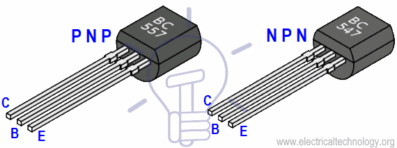
How to Remember the direction of PNP & NPN Transistor?
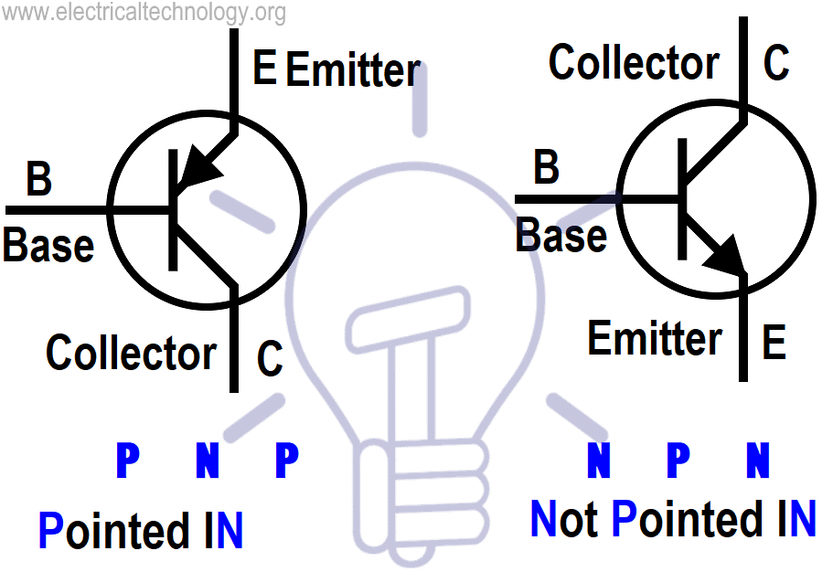
- PNP = Pointed In
- NPN = Not Pointed In.
If you think that is a little bit complex, then try the more simple one as follows.
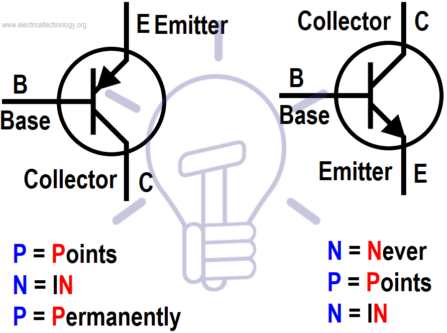
Click image to enlarge.
PNP NPN
- P = Points N = Never
- N = IN P = Points
- P = Permanently N = iN
Now let’s move to the step by step tutorial to know how to check and test a transistor?
Test a Transistor using Digital Multimeter in Diode or Continuity Mode
To do so, follow the instructions given below.
- Remove the transistor from the circuit i.e. disconnect the power supply across the transistor which has to be tested. Discharge all the capacitors (by shorting the capacitor leads) in the circuit (If any).
- Set the meter on “Diode Test” Mode by turning the rotary switch of the multimeter.
- Connect the Black (common or -Ve) test lead of the multimeter to the 1st terminal of the transistor and Red (+Ve) test lead to the 2nd terminal (Fig below). You have to perform 6 tests by connecting the Black (-Ve) test lead and Red (+Ve) test lead to 1 to 2, 1 to 3, 2 to 1, 2 to 3, 3 to 1, 3 to 2 respectively by just replacing the multimeter test leads or reverse the transistor terminals to connect, test, measure and note the reading in the table (shown below). Numbers in Red colors are Red Test Lead and numbers in Black are connected to Black (-Ve) test lead of multimeter.
- Test, measure and note the display reading shown in the multimeter in the table below.
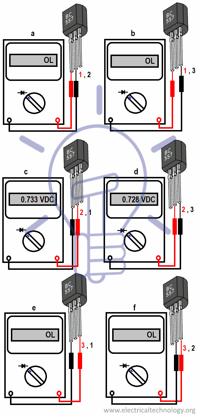
We have the following data from the table given below.
Out of 6 tests, we got data and results only on two tests i.e. points 2 to 1 and 2 to 3. Where we got at points 2 to 1 is 0.733 VDC and 2 to 3 0.728 VDC. Now, we can easily find the type of transistor as well as their collector, base and emitter.
- Point 2 is Transistor Base in BC55 Transistor.
- BC 557 is a PNP Transistor where the 2nd (middle terminal is base) connected to Red (+Ve) test lead of the multimeter.
- At all, Terminal 1 = Emitter, Terminal 2 = Base, and Terminal 3 = Collector (BC 557 PNP Transistor) because, the test result for 2-1 = 0.733 VDC and 2-3 = 0.728 VDC, i.e. 2-1 > 2-3.
BC 557 PNP |
Measuring Points | Result |
| 1-2 | OL | |
| 1-3 | OL | |
| 2-1 | 0.733 VDC | |
| 2-3 | 0.728 VDC | |
| 3-1 | OL | |
| 3-2 | OL |
Finding BASE of Transistor:
As mentioned in the above tutorial, the common number found in the tests above is base. In our case, 2nd terminal is Base and 2 is common out of 1-2 and 2-3.
2nd Method using DMM to find the Base of the Transistor.
If you follow the same pattern and connecting method of multimeter leads and transistor terminals one by one in the figure shown above, in fig “c” and “d” , The Red (+Ve) test lead is connected to the middle one i.e. 2nd terminal of lead and the Black (-Ve) test lead is connected to the 1st one terminal of transistor.
Again, The Red (+Ve) test lead is connected to the middle one i.e. 2nd terminal of lead and the Black (-Ve) test lead is connected to the 3rd one terminal of transistor and multimeter shows some reading i.e. 0.717 VDC & 0.711 VDC respectively in the case of BC 547 NPN.
The common lead is 2nd one connected to Red (+Ve) test lead (i.e. P and yes, the other two leads are N) which is base. The case is reversed in the case of the BC 557 PNP transistor.
NPN or PNP?
It’s simple. If the Black (-Ve) test lead of the multimeter is connected to the base of the transistor (2nd terminal in our case), then it is PNP transistor, and when Red (+Ve) test lead is connected to the base of the terminal, It is NPN transistor.
Related Posts:
Emitter or Collector?
EB (Emitter – Base) forward bias is greater than CB (Collector – Base) i.e. EB > CB in PNP Transistor e.g. BC557 NPN. Hence, It is a PNP Type Resistor. In NPN Transistor, BE (Base – Emitter) forward bias is greater than BC (Base – Collector) i.e. BE > BC, e.g. BC 547 PNP.
Here is the conclusion.
- Point 2 is Transistor Base in BC547 Transistor
- BC 547 is a NPN Transistor where the 2nd (middle terminal is base) is connected to Red (+Ve) test lead of multimeter.
- At all, Terminal 1 = Emitter, Terminal 2 = Base, and Terminal 3 = Collector (BC 547 NPN Transistor) because, the test result for 1-2 = 0.717 VDC and 2-3 = 0.711 VDC, i.e. 1-2 > 2-3.
BC 547 NPN |
Measuring Points | Result |
| 1-2 | 0.717 VDC | |
| 1-2 | OL | |
| 1-3 | OL | |
| 1-3 | OL | |
| 2-3 | OL | |
| 2-3 | 0.711 VDC |
Check a Transistor using Analog or Digital Multimeter in Ohm (Ω) Range Mode:
Steps:
- Disconnect the power supply to the circuit and remove the transistor from the circuit.
- Rotate the selector switch and put the Multimeter knob in Ohm Range (OHM)
- Connect the Black (common or -Ve) test lead of the multimeter to the 1st terminal of the transistor and Red (+Ve) test lead to the 2nd terminal (Fig 1 (a). (You have to perform 6 tests by connecting the Black (-Ve) test lead to 1 to 2, 1 to 3, 2 to 1, 2 to 3, 3 to 1, 3 to 2 respectively by just replacing the multimeter test leads or reverse the transistor terminals to connect, test, measure and note the reading in the table(shown below). (Numbers in Red colors show the transistor leads connected to the Red (+Ve) test lead of multimeter and the numbers in black colors show the transistor leads connected to the Black (-Ve) test lead of multimeter. (Better explanation in the table & fig below)
- If the multimeter shows high resistance in both first and second tests by changing the polarity either of transistor or multimeter, as shown in Fig 1 (a) and (b). (Note that, the result will be shown only for 2 tests out of 6 as mentioned above). i.e. In our case, the 2nd terminal of the transistor is BASE, because it shows high resistance in both tests of 2 to 3 and 3 to 2 where Red (+Ve) test lead of the multimeter is connected to 2nd terminal of the transistor. In other words, the common number in tests is Base which is 2 out of 1, 2 and 3.
Click image to enlarge
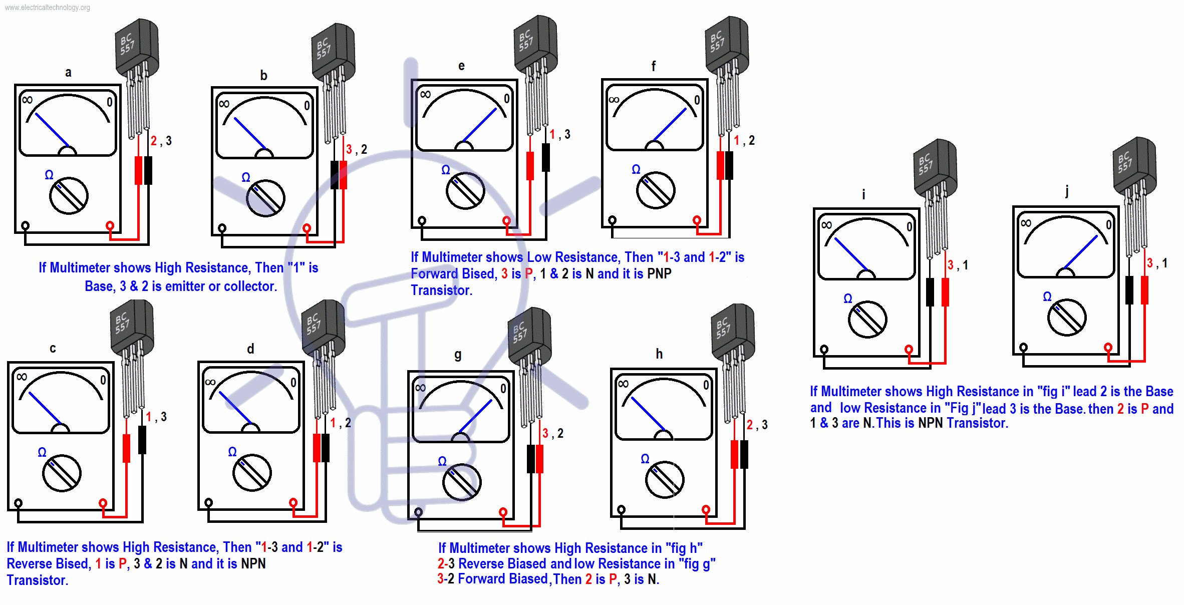
PNP or NPN ?
Now, it is a NPN transistor because, it shows reading only when the RED (+Ve) test lead (i.e. P terminal where P = Positive) is connected to the Base of the transistor (See fig below). If you do the reverse, i.e. Black (-Ve) test lead (i.e. N = where N = Negative) of multimeter connected to the transistor terminal in sequence of (1 to 2 and 2 to 3) and shows reading in both tests as above, The 2nd Terminal is still BASE, but the transistor is PNP ( see fig below).
Testing a Transistor using Digital Multimeter in the Transistor or hFE or Beta Mode
hFE also known as beta is dc gain stands for “Hybrid parameter forward current gain, common emitter” used to measure the hFE of a transistor which can be found by the following formula.
hFE = βDC = IC / IB
It also can be used to check a transistor and its pin terminal as shown in fig 1.
To check a transistor in hFE mode, there are 8 pins slot in the multimeter indicated by PNP and NPN as well as E C B (Emitter, Collector and Base). Simply put the three pins of transistor in the multimeter slot one by one in different slots i.e. ECB or CBE (Rotary knob should on hFE mode).
If they display reading (It would be the hFE reading of transistor) , In our example, We used BC548 Transistor which shows the beta value of 368 (CBE position) the current position on the C, B, E slot are the exact terminals of transistor i.e. collector, base and emitter) and transistor is in good position, otherwise, replace with new one.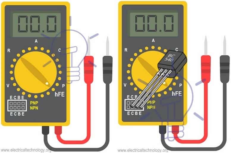
Related Posts:
- How to Test a Capacitor using Digital & Analog Multimeter – 8 Methods
- How to Test a Diode using Digital & Analog Multimeter – 4 Ways.
- How to Test a Relay? Checking SSR & Coil Relays?
- How to Test & Fix the Printed Circuit Board (PCB) Defects?
- How to find The value of Burnt Resistor (By three handy Methods)
- How to Test for Continuity in Electrical Components with Multimeter?
- Cable and Wire Tester Circuit Diagram
- How to test a battery with Test meter?
- How To Test Electrical & Electronics Components using Multimeter?


Direction of NPN should be reversed in 2nd picture
Thanks for Correction..
good<br />
OK How about the arrow ALWAYS points to the negative charged region of ALL semiconductors. Conventional current flow geeks like engineers. Well then reverse it and think backwards. The arrow points to the negative region. Period
The second picture is incorrect.
THANK YOU
Hello sir,<br />I have a doubt,may you give answer?<br />what is the change in eddy current loss with freqency in 3 ph. Induction motor?
In first picture, Emitter and Collector should be reversed. I think, terminal having ARROW is always Emitter in both PNP and NPN transister.
how do we note the emitters;base and collector of a PNP and npn
nice trick
Let us consider two things,
1. Positive Negative Positive (PNP), Negative Positive Negative (NPN)
2. Current flows from positive (P) to negative (N) termianal ( P to N)
so now,
PNP – positive is outside and negative is inside (Arrow comes from outside to inside)
NPN – positive is inside and negative is outside (Arrow goes from inside to outside )
wo is mit dia du fotz dei npn is foi hi
Can one still use an ohmmeter for such operations
Yes You can.. Method is already mentioned above.
Red indication to number changed….
Thanks for sharing such a beautiful article. It’s very helpful to me. Please keep more sharing about PNP transistor