How to Measure Current using Digital and Analog Multimeter?
Measuring of AC and DC Current with a Multimeter? (DMM + Analog)
Just like voltage, current measurement is also necessary for troubleshooting any circuit. It is used to check if a certain circuit or load is operating properly or is it drawing too much current.
A multimeter (also known as AVO meter “Ampere – Volt – Ohm” is the basic tool for measuring the different electrical quantities such as current, voltage, resistance, capacitance, transistors, diodes, temperature and continuity in wires, fuses, resistors, circuit breakers, and other faulty components and devices.
In this tutorial, we will measure the AC and DC current using DMM and analog multimeter as well as clamp-meter with step by step guide.
What is Electric Current?
Current is the rate of the amount of charge flowing. It is measured in Amperes (shortly Amps). AC current changes direction continuously while the DC current flows in only one direction. The meter used for current measurement is called Ammeter.
As the current is the flow of charge, while measuring the current, we need the current to flow inside the meter. Therefore, the circuit must be opened at the point of measurement and the meter must be inserted in line with the circuit. However, the clamp meter allows you to measure the current without opening the circuit.
Related Post:
- How to Measure Voltage using Digital and Analog Multimeter?
- How to Check a Capacitor with Digital (Multimeter) and Analog (AVO Meter)
Measuring AC Current using Digital Multimeter:
- Turn off the power supply to the circuit.
- Switch ON the multimeter.

- Turn the knob to AC current “Ô (denote by letter A with wavy “~” sign on top of it).

- Set the current range of the meter by turning the dial. The range should be selected to the largest expected value. Use maximum range for unknown current.

- Insert the black probe into the COM (common) socket of the meter.
- Insert the red probe into the current socket having the letter “A” or “mA” on it.
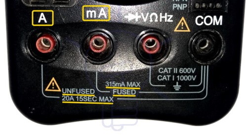
- Most DMM has separate sockets for low current (fused) and high current (unfused). The low current socket is usually identified by having mA written on it. Use the socket according to the expected current range. Otherwise, you may damage the meter.

- Break the circuit at the point of measurement.
- Connect the black probe to one of the two points at the point of measurement
- Connect the red probe to the other point at the point of measurement.

- Turn ON power supply to the circuit.
- Note the reading from the meter. DMM provides simple and easy to read numbers on its screen.
- If the range is set at maximum, reduce it using the selector knob to increase the accuracy.
- Once the measurement is complete, switch off the power supply to the circuit.
- Remove the red probe first and then the black probe.
- Rotate the knob back to voltage or resistance position and switch off the multimeter. If you want to keep the probes inserted in the meter, try to place the probes in the voltage socket.
Note: Do not touch the tips of the lead even if one of them is connected. Do not touch the wires with bare hands. Do not allow the tips of the lead to connect with one another. Be very careful when working on AC current of the mains as it can shock or electrocute a person if necessary precautions are not taken.
- Related Post: How to Test a Diode using Digital & Analog Multimeter
Measuring AC Current using Analog Multimeter:
- Turn off the power supply to the circuit.
- Switch ON the Analog multimeter.
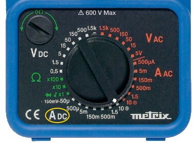
- Turn the knob to AC current “AAC” or “Ô (A with wavy “~” sign on top of it).

- Set the current range of the meter by turning the dial.
 Note: These ranges represent the FSD (Full Scale Deflection).
- Insert the black probe into the COM (common) socket of the meter.
- Insert the red probe into the current socket having the letter “A” or “mA” on it.
- There are two sockets; low current and high current socket. Usually, the low amp socket has “mA” and the high amp socket has “A” written on it. if the current is unknown use a high amp socket. 10A in this example.

- Break the circuit at the point of measurement.
- Connect the meter in series with the circuit by connecting the black probe first and the red probe second.
- Turn ON power supply to the circuit.
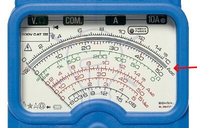
- Note reading from the AC current scale (not DC current scale).

- Ensure the deflection is maximum by decreasing the current range using the knob to increase its accuracy.
- Once the measurement is complete, switch off the power supply to the circuit.
- Remove the red probe first and then the black probe.
- Rotate the knob back to voltage or resistance position and Switch off the multimeter.
Note: Most lower-end analog multimeters do not include AC current measurement due to the difficulty of stepping up the voltage.
AC current does not have polarity. Therefore, it does not matter if you swap the probes, the reading will still be the same. Do not overload the analog meter to avoid any potential damage. Overloading occurs when the current is higher than the selected range of the meter.
- Related Post: How to Check a Transistor by Multimeter (DMM+AVO)
Measuring DC Current using Digital Multimeter:
- Switch off the power supply to the circuit.
- Turn the meter ON by pushing the ON/OFF button or turning the knob.
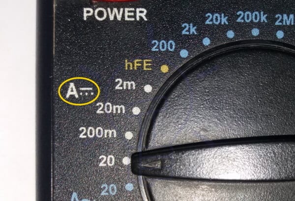
- Turn the dial to DC Current (DC with straight light and 3 dots on top of it).
- Select a suitable range higher than the expected reading using the selector knob.

- Insert the back probe into the COM (common) socket.
- Insert the red probe in one of the two current sockets; low current (fused) and high current (unfused). The low current socket is identified by “mA” having range in mA with high accuracy. While the high current socket (identified by “A”) has range in amperes.
- Use the high current socket for unknown current as it will blow the fuse inside the meter if a high current flows through it.
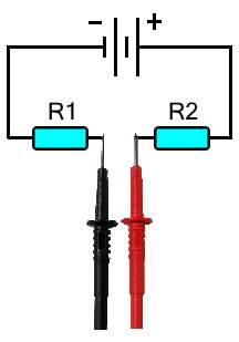
- Break the circuit at the point of measurement. Since it is a DC circuit, polarity at the point of measurement must be considered.
- Connect the black lead with the lower or negative voltage point.
- Connect the red lead with the positive or higher voltage point.
- Switch the circuit ON.
- Note the reading in the multimeter.
- Reduce the range to get maximum accuracy.
- Once the measurement is complete, switch OFF the circuit, remove the red probe first and then the black probe from the test points.
- Either remove both probes from the Multimeter or place them in the voltage resistance socket to avoid being damaged by connecting it to high voltage.
- Switch Off the multimeter.
Note: It is safe to work and touch a DC circuit at low voltage. However, it is best not to touch the tip of the leads during reading as it may inflict errors in the measurement. Do not touch the tips of the leads together. Mind the polarity of the DC circuit, it does not damage the DMM but shows a negative sign to show the opposite direction of the current.
- Related Post: How to Perform the Continuity Test with Multimeter?
Measuring DC Current using Analog Multimeter:
- Turn off the power supply to the circuit.
- Switch ON the Analog multimeter.
- Rotate the knob to DC current “ADC” or (DC with a straight line having 3 dots with it).
- Set the current range greater than the expected reading by turning the dial.

- Insert the black probe into the COM (common) socket.
- Insert the red probe into the current socket having the letter “A” or “mA” on it.
- Low current socket has a maximum range in milliAmperes “mA” and high current has a maximum range in Amperes “A”. Use the proper socket according to the expected reading.
- If unsure of the current, use the high current socket.
- Break the circuit at the point of measurement. Mind the polarity because it is direct current.
- Connect the meter in series with the circuit by connecting the black probe with the negative and the red probe with the positive voltage point.
Note: Connecting the probes in reverse may damage the analog meter. Because its needle cannot deflect in the reverse direction.
- Turn ON power supply to the circuit.
- Note reading from the DC current scale “A DC” (not to be confused with AC current scale).
- Reduce the current range to have maximum deflection and accurate reading.
- Once the measurement is complete, switch off the power supply to the circuit.
- Remove the red probe first and then the black probe.
- Rotate the knob back to voltage and Switch off the multimeter.
- If you don’t want to remove the probes, place them in the voltage socket to avoid any damage of accidentally connecting it with high voltage.
Note: Mind the polarity while using an analog multimeter to measure DC current. It will not show any deflection when connected with opposite polarity. It may cause damage to the meter.
- Related Post: How to Test a Relay? Checking SSR & Coil Relays
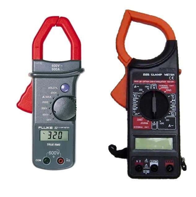
How to Measure Electric Current using Clamp Meter?
The clamp meter has a built-in clamp-on probe that is only used for measuring current. it is also available as a separate probe. The advantage of the clamp meter is that It does not require you to break the circuit or de-energize it. In fact, it is very safe to use even with measuring high current. It works on the magnetic field produced by the flowing charges.
- Switch on the clamp meter.
- Turn the knob to current (either AC or DC)
- Set the range higher than the expected reading.
- Clamp the meter to the wire.
- Note the reading in the meter.
- Reduce the range of the meter to get an accurate reading.
In case of Clamp Probes for DMM
Current clamp probe converts the AC or DC current into respective voltages that is directly proportional to the current. To get the current readings, the voltage must be converted into current.

Every current clamp probe has its specific current-voltage conversion ratio for a specific current range. For example a clamp probe having 10mv/A for 10 Amp range shows a reading of 50 mv. Thus the current is 50/10 = 5 Amps.
- Turn the knob of the DMM or analog meter to AC or DC voltage for AC or DC current accordingly.
- Set the range higher than the expected value. Use low range for high accuracy.
- Insert the black probe of the clamp probe into the COM socket.
- Insert the red probe into VAC or VDC for AC or DC current respectively.
- Clamp-on the current clamp probe to the line.
- Note the reading of the meter which should be in voltage.
- Divide this voltage by the conversion ratio of the probe. The result is the measurement of the current.
Note: if the meter is clamp to more than one line, their magnetic field will cancel out each other and the readings will be wrong.
- Related Post: How to test a battery with Test meter?
Milliampere and Ampere Ranges
Most multimeters have a separate socket for low current “mA” and higher current “A” ranges. The low current socket always has a fuse while in some expensive DMMs, the higher current socket has a fuse as well.
The mA socket has very low ranges usually below 200mA. While the higher current socket is used for ranges about 20 or 30 Amperes depending on the meter. The low current socket provides high accuracy and resolution at low-level current. However, it cannot handle large current. Therefore, it has an internal fuse rated around 315 mA.
The low current socket should not be used for testing higher current as it can blow out the fuse which will render the ammeter useless.
Ammeter in Parallel
Ammeter has a very small shunt resistance usually less than 1 ohm. If it is accidentally connected to a circuit in parallel, the high voltage will appear across this small resistance. Due to this high voltage, a huge current will flow through the meter that will damage it.
For this reason, the ammeter has a fuse that is used for protecting the meter in such a situation. The fuse blows out if the current exceeds a certain limit.
Related Post: How to Test & Fix the Printed Circuit Board (PCB) Defects?
Checking the Fuse
When the fuse blows out, the ammeter stops working. It does not show any reading, since the fuse broke the path for the current flow. It is necessary to check the fuse before doing any measurement.
In order to check the fuse, connect the multimeter in resistance mode by turning the selector knob. Place the probes in the “COM” and “mAVΩ” socket if your meter has the same socket for voltage, resistance and low current measurement. If your meter has a dedicated socket for low current measurement then place the black probe in VΩ socket and the red probe in the mA socket.
Now connect the probes together. If the readings show low resistance in the range of a couple of ohms, it means the fuse is intact and it is working properly. If the meter is showing “OL” or very high resistance, the fuse is blown and it must be replaced.
DC Polarity
Direct current DC is unidirectional current, unlike AC. Therefore, its direction and polarity matter. If the probes are connected with opposite polarity, it will not damage a digital multimeter but only show a negative “-” sign. But if an analog multimeter is used, the reverse current may damage the meter because the needle cannot deflect in opposite direction and if the voltage is high it may damage it.
Related Multimeter Tutorials:
- How to Test Electrical and Electronics Components and Devices with Multimeter
- Basic Electrical and Electronics Engineering Tools
- How to Find The Suitable Size of Cable & Wire for Electrical Wiring Installation?
- How to Find the Proper Size Outlets, Receptacle and Switch?
- How to Find the Right size of circuit breakers?
- How to Calculate the Value of Resistor for LED’s?
- How to Calculate the Battery Charging Time & Charging Current? Example
- How to Find the Proper size of Earth Conductor, Earth Lead and Earth Electrodes?
- How to Find The value of Burnt Resistor? (4 Methods)


