What is Multimeter? Working of Analog and Digital Multimeters
What is Multimeter? Types, Functions Working and Applications
Electrical and electronics engineering students, engineers and technicians use various kinds of measurement devices to check various electrical quantities in a circuit such as voltage, current, continuity, power etc and check and test various electronic components such s diode, transistor, relay, capacitor, resistor etc.. A multimeter that is capable of performing different tests and measurements is used in labs and industries for repairing and troubleshooting of electrical devices and equipment.
What is a Multimeter?
A multimeter is an electrical measuring instrument used for measuring voltage, current, resistance, and other electrical parameters. It can measure “multiple” electrical quantities that depend on the type of multimeter.
They are handheld devices that vary in size, precision, and accuracy. They are mostly used by electricians, engineering students, and hobbyists for troubleshooting electrical devices and circuits.
It has an LCD or scale, a dial, testing probes and ports. The LCD or scale is used for displaying the measurement. The dial has multiple functions that can be selected by turning the knob. The testing probes are used for connected the meter to the circuit. The ports are used for inserting the testing probes into the meter.
- Related Post: Difference between Analog and Digital Multimeter
Working of Multimeter
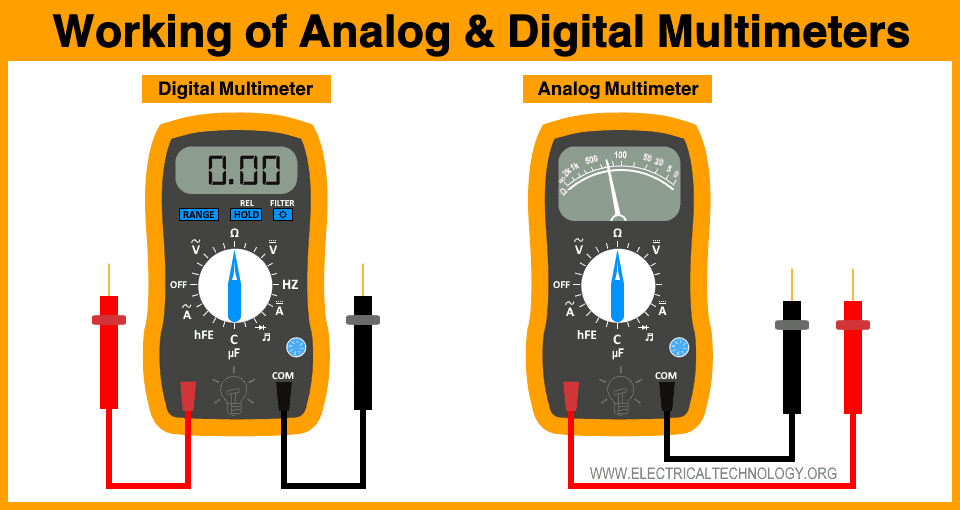
A multimeter can be either analog or digital. However, both types of multimeters have the same working procedures.
It has a dial that is used for selecting the required measurement. it has multiple measurement symbols written on it. The dial is rotated to select measurement. it can also select the proper range for the measurement. Some meter has auto range features.
It has two probes i.e. black and white. The black probe is always inserted in the black “COM” or common port while the red probe is inserted into one of the other red ports according to the measurement.
The probes are used to connect the meter to the circuit. The internal circuit of the multimeter measures the selected parameter and displays its reading on the LCD or scale.
However, the precaution and the configuration used for connecting the multimeter to the circuit or a component varies with the type of measurement.
Functions
A multimeter has multiple functions that depend on the type of the multimeter. These functions can be activated by using the selection dial as well as some buttons. Its main function is to measure current, voltage and resistance. Here are some of the functions available in a multimeter:
| Function | Description | Symbol |
| AC Voltage | Measure AC Voltage | V~ |
| DC Voltage | Measure DC Voltage | V⎓ |
| AC Current | Measure AC Current | A~ |
| DC Current | Measure DC Current | A⎓ |
| Resistance | Measure resistance of a circuit or component | Ω |
| Frequency | Measure frequency of a signal | Hz |
| Duty Cycle | Measure the duty cycle of the signal | % |
| Diode Test | Checks a diode in a circuit | |
| Capacitance | Microfarad, measure capacitance in microfarads | μF |
| Continuity | Gives an audible indication for continuity between two points. | |
| Transistor Test | The forward current gain of a transistor | hFE |
| Relative Mode | Measure the offset value. Used for accurate measurement of small values | REL |
| Temperature | Measures temperature in Fahrenheit or Celsius | F°, C° |
Types of Multimeter
There are two main types of multimeter i.e. analog multimeter and digital multimeter.
Analog Multimeter
Analog multimeter is the oldest form of a multimeter. it has a needle that rotates along a scale. They are cheap but are difficult to read. However, they are more sensitive than a digital multimeter. It can sense even small changes in the readings.
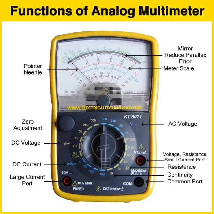
It is made of a coil placed between two permanent magnets. A needle is placed on top of the coil. When a current passes through the coil, it generates a magnetic field that interacts with the magnetic field of the permanent magnet. As a result, the coil rotates moving the needle along the scale. The angle of rotation depends on the amount of current flowing through the coil. This configuration is also known as a galvanometer. It has a very small resistance therefore, it is more sensitive.
Due to the same reason, Full Scale Deflection (FSD) should be avoided. Because the current exceeds the range of the coil deflection and it starts to burn the coil which will destroy the meter itself. Therefore, the multimeter has multiple ranges where shunt resistors are used in parallel to divide the current and measure larger values.
Analog multimeter is difficult to read for beginners because it has multiple scales on a single dial. You have to spot the selected scale and sometimes it requires you to multiply the reading by 10 or 100 to get the final measurement for larger ranges. The needle can also cause parallax error where you have to look at exact 90 degrees at the scale to get a precise reading.
Advantages
- It does not require a battery to measure voltage and current.
- It is very sensitive.
- It can detect small changes in the reading in real-time.
- It has a quicker response time for checking continuity or leakage.
- It is cheaper than a digital multimeter.
- It can show fluctuations in current and voltages.
Disadvantages
- Full scale deflection or “overloading” can damage the analog multimeter
- It is difficult to read from the analog scale.
- There are different uncertainties in the reading.
- It can cause parallax error.
- They are physically not very strong.
- They do not have extra features such as in digital multimeter.
- Unable to show negative values.
- It has Low input impedance that affects the circuit due to the loading effect.
- It requires “zero adjustment” to adjust the needle.
Digital Multimeter
A digital multimeter or DMM measures electrical quantities and shows them on an LCD screen. It computes the readings digitally and displays them on an easily readable digital screen. On the other hand, the analog multimeter displays the readings without any computation thus having a quick response time.
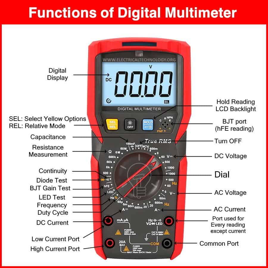
It has an LCD, a dial and multiple ports. The dial includes internal circuitry that is connected through a trace of concentric rings. The knob is used to activate a circuit for specific measurements.
Digital multimeter includes a microprocessor to compute readings. However, the input voltage or current is in analog form. Therefore, an ADC (analog to digital converter) is included to convert the readings and display them on the LCD screen. The LCD makes the measurement easily readable as opposed to the scale on an analog multimeter.
The dial is also used to select from multiple ranges having different shunt resistors. When the measurement exceeds the range, the multimeter overloads. Therefore, it has overload protection. Some DMMs have auto range features that automatically select the proper shunt resistor for the measurement to avoid overloading.
Advantages
- The readings are easy to read from the LCD display
- The readings are more accurate.
- There are fewer uncertainties and no parallax error.
- It has a high input impedance that does not affect the circuit.
- They are physically robust.
- It can show both positive and negative readings.
- It has extra added features such as capacitance, frequency, temperature measurement.
- There is no requirement for zero adjustment.
- It can record and display minimum and maximum values of reading.
- Auto range feature allows selecting a suitable circuit for the measurement and avoid any potential damage to the meter.
Disadvantages
- It requires a battery for any kind of measurement.
- They are expensive than an analog multimeter.
- It cannot detect fluctuations in readings.
- It has a slower response time due to computation.
- It has a voltage limit due to sensitive electronic circuitry.
Terms of Multimeter
There are several terms used for multimeters that define how good and reliable the multimeter is.
Sensitivity
The sensitivity of the multimeter is defined as the resistance offered per volt of full-scale deflection by the multimeter. Its unit is ohm/volt (Ω/V).
Sensitivity shows the internal resistance of a meter. If a meter has high sensitivity, it has high internal resistance. Such meters do not affect the circuit for voltage measurement. it draws no current from the circuit.
Resolution
The resolution of a multimeter is defined as the smallest change in the electrical parameter (current, voltage, resistance, etc.) it can detect and display.
For example, a resolution of 1mA at the range of 400mA means the multimeter can detect 1mA of change in the reading.
A multimeter that has a smaller resolution and has more accurate reading.
Range
The range of the multimeter is the maximum value the circuitry of the meter can measure. It is related to the resolution of the multimeter. If the range is lower, it has a smaller resolution. The resolution increases with the range.
If the measurement exceeds the range, it overloads the multimeter. Therefore, the best and accurate reading is obtained at the lowest range without overloading the meter.
Accuracy
The accuracy of a multimeter is defined as the largest allowable error in a measurement. It shows how close the reading in to the actual measurement. it is expressed in %.
For example, a multimeter having ±1% accuracy has reading of 100 ohms. Then the actual reading can be 99 ohms or 101 ohms.
If a multimeter has low % accuracy, it has a more accurate reading.
Precision
The precision of a multimeter refers to how close the measurements are when they are repeated under the same conditions. It tells if the multimeter is reliable and its measurement does not change.
Precision also identifies the error pattern in the multimeter that can be compensated.
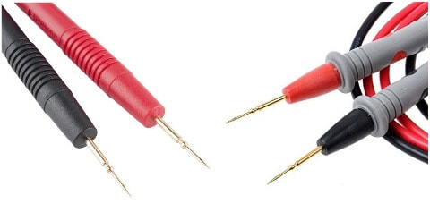
Probes
The probes of a multimeter are used to connect the meter to a circuit or a component. Their one end is inserted into the port of the meter called banana jack. While the other end is connected to the circuit called probe tips and they can be of various types.
Type of Multimeter Probe Tips
There are several types of multimeter probes that are classified based on its shape and function. However, their main function is to connect the meter to the circuit.
Black and Red Probe
The probes can be mainly classified into black and red probes. The black probe inserts into the “COM” or common port of the meter. It is connected at a lower voltage point.
The red probe inserts into one of the other ports depending on the selected measurement such as voltage, current and resistance. It is connected to the higher voltage point of the circuit.
Pointed Probes
These are the most common type of probes and are the cheapest of them all. They are commonly used for any kind of reading. They are suitable for quick and frequent use.
Alligator Clip
The alligator clip or crocodile clip is a spring-loaded metal clip that has serrated teeth that resemble the jaw like an alligator, thus its name. It makes a firm connection and holds on to the wire. They are suitable for a long-term test.

The con of the alligator clip is that it has a wider tip and it gets wider when it opens. It can touch or create a short circuit with adjacent wires. Therefore, it is not suitable for use in tight spaces such as circuit boards and IC.
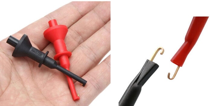
Retractable Hook Clips
Retractable hook also known as J-hook or IC test leads has hooks for tips. It has a narrow tip that is retractable. It is used for makes a secure connection in tight spots. The hooks make it easier to hold-on to closely packed small wires and pins.
Tweezer Probes
As the name suggests, such probes are designed in the shape of tweezers. They are used for testing between closely spaced points such as in SMDs (surface mount devices)

Clamp Probes
Clamp probes clamp around a conductor and measure the current flowing through it without physically touching the conductor. Clamp probes are peripheral used for safely measuring current in a circuit. it converts the current into voltage where the conversion ratio is used to calculate the measurement.

The clamp meter has built-in clamp probes used for directly measuring current and displaying the current value on its LCD.
How to Use a Multimeter?
A multimeter (either digital or analog multimeter) can be used to measure many electrical quantities, analyze and troubleshoot different electrical components & devices. We have already shared the step by guide and pictorial tutorials which show how to use a multimeter to test and measure specific quantities and devices.
- How to Measure Capacitance using Multimeter?
- How to Test a Capacitor using Digital and Analog Multimeters?
- How to Measure Frequency using Multimeter?
- How to Measure Power using Digital and Analog Multimeter?
- How to Measure Resistance using Digital & Analog Multimeter?
- How to Measure Voltage using Digital and Analog Multimeter?
- How to Measure Current using Digital and Analog Multimeter?
- How to Test a Diode using Digital & Analog Multimeters?
- How to Test a Relay? Checking SSR & Coil Relays?
- How to Check a Transistor by Multimeter (DMM+AVO)?
- How To Perform a Continuity Test for Electrical Components using Multimeter?
- Testing Electrical and Electronics Components and Devices using Multimeter
Safety Precautions
While using a multimeter, the following precautions must be followed to avoid any kind of accident.
- Do not touch the tip of the test leads while taking measurements.
- Do not use broken test leads.
- Do not connect the meter in parallel to a circuit for current measurement.
- Do not connect the meter to a voltage source when the probes are connected in Ampere sockets.
- Do not connect the meter to a powered-on circuit for resistance measurement.
- Do not connect a charged capacitor to a meter.
- Do not use the multimeter for higher voltage than the one mentioned in its guide.
- Replace the battery when the display shows a low battery indication.
- Always remove the test probes after using or place them in the voltage measurement port.
Applications of Multimeter
There are different kinds of multimeters ranging from a few dollars to thousands of dollars. The more expensive the multimeter, the more features and functions it has. Some of the basic applications of the multimeter are:
- To measure voltage.
- To measure current.
- To measure resistance.
- To test the continuity in a circuit.
- To measure temperature.
- To measure the frequency of a signal.
- To measure the capacitance of a capacitor.
- Test a diode, check a transistor, troubleshot a relay and test other electronics components.
These basic functions of multimeters are used for troubleshooting any kind of electrical circuit such as
- Voltage measurement is used to know the health of a battery.
- It also tells if an outlet or a switch is working properly.
- The current measurement tells the condition of the load, either it’s drawing normal current or too much.
- The continuity test or resistance test detects any broken connection or cable.


I want a multimeter