How To Perform a Continuity Test for Electrical Components with Multimeter?
What Is Continuity Test & How To Test for Continuity? Continuity Test For Different Electrical & Electronic Components & Devices
In Electronics & Electrical systems, electrical wiring installations, maintenance, troubleshooting and repairing works. a continuity test is checking of a circuit to see if the current can flow through it or not. It basically determines if a circuit is open or closed.

What is Continuity Test?
Continuity Test is the testing of an electrical circuit to determine if the current can pass through it (known as close or complete circuit).
In a continuity test, a small voltage is applied to the two points of the circuit that need to be checked. The current flow between these two points determines if it’s an open or closed circuit. Usually, there is a buzzer or led in series (inside continuity meter) to identify if the current flows through it or not.
A close-circuit provides a closed path for the current flow & an open circuit does not allow the current flow. These circuits can be distinguished using the continuity test.
- Related Post: How to Test a Capacitor by Digital & Analog Multimeter ?
Why Do We Use Continuity Test?
Continuity test very important test in troubleshooting of any circuit. Various uses of continuity tests are:
- To check the wire connection inside the circuit. These wires may be broken.
- It is used for Identifying damaged component.
- It is also used for checking the quality of soldering.
- It is used for identifying a specific wire or electrical connection.
Procedure Of Continuity Test
There are mainly two methods for checking the continuity of a circuit using a multimeter.
The first method is to use the continuity mode in the multimeter, which is specially made for this purpose.
The second method is to use the Ohmmeter.
Using Continuity Mode
The steps for continuity test using continuity mode is given below:
- De-energize the circuit, if it has any power input.
- Set the dial of the multimeter in continuity mode (continuity mode is shown by the symbol of sound)
- Insert the black probe into the COM port.
- Insert the red probe into the V, Ω port.
- Now touch the probes with each other. If the meter beeps or gives reading 0 that means the meter works fine.
- Now connect the probes to both ends of the component or wire that you want to test.
- If the meter shows 0 and beeps, it means the path is complete (close) or the component allows the flow of current.
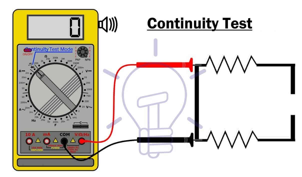
- If the meter does not beep & show 1 or OL, it means the path is broken (open) or the component does not allow the flow of current.
The continuity in non-directional, it does not matter which probe should be connected to which side. The result is always the same except some cases like diodes which allow the flow in only one direction.
- Related Post: How to Test a Relay & Relay Coils by Multimer?
Using Ohm-Meter
An Ohmmeter can also be used to determine the circuit whether it is a closed or open circuit, which is the main purpose of a continuity test.
Steps for continuity test using an ohmmeter
- First de-energize the circuit, if it has any power source.
- Set the dial of the multimeter to resistance mode Ω. If it has many ranges, set the dial to the minimum range.
- Insert the black probe into the COM socket of multi-meter.
- Put the red probe into the V, Ω socket.
- Connect the probes to both ends of the wire or component you want to test.
- If the meter reads 0 Ohm or near to 0 Ohm, the path is complete and close.

- If the meter reads 1 or OL, the wire connection is broken (open).
Related Post: How to Test a Diode using Digital & Analog Multimeter?
Continuity Test For Capacitor
You can test a capacitor using the continuity test.
- Remove the capacitor if it is in a circuit.
- Discharge it carefully if charged.
Using Continuity Mode
- Set the Multi-meter in continuity mode & insert the black & red probe as described above.
- Place the red and black probes of multi-meter across positive & negative terminals of the capacitor respectively.
- If the capacitor is good, the reading should start from ‘0’ as the capacitor is charging from the multi-meter. The reading will increase & eventually becomes infinity or OL, which means that the capacitor became fully charged & open.
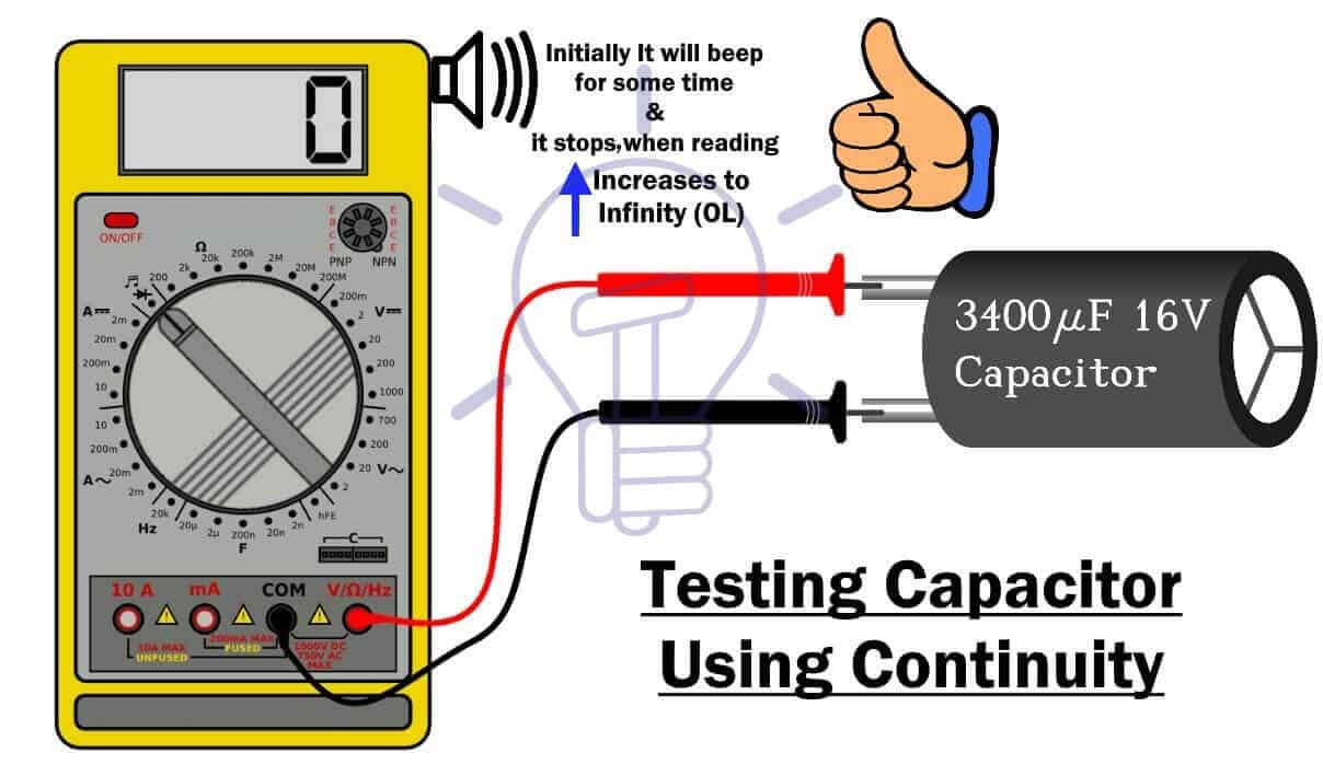
- If a capacitor is damaged, multi-meter will either show very low value (short) or infinity OL (open).
Related Post: How to Check a Transistor by Multimeter (DMM+AVO) ?
Using Resistance Mode
- Set the dial of the multimeter in resistance mode.
- Place the red probe on the positive terminal and black probe on the negative terminal of the capacitor
- If the resistance starts increasing from 0 Ohm to infinity, the capacitor is good. Because it was charging at the beginning.
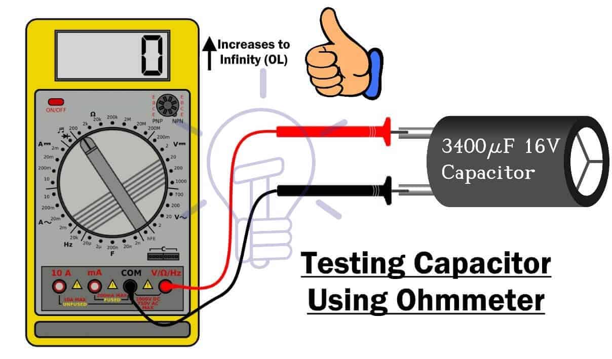
- If the meter reads very high resistance initially even when it was discharged, the capacitor is damaged (open).
- If the readings show very low resistance, the capacitor is short.
Related Post: How to find The value of Burnt Resistor ?
Continuity Test For Inductor:
You can also test an inductor using the continuity test.
An inductor is a coil & both terminals of the coil are electrically short.
- First, you need to remove the inductor from its circuit. It can be tested while connected in a circuit but it depends on the circuit itself. Best way to test it is to remove it.
Using Continuity Mode
- Turn the knob of Multi-meter in continuity mode.
- Insert the black & red probe in COM & V-ohm jack respectively.
- Place the probes of multi-meter across both terminals of the Inductor respectively.
- If the Inductor is good, the multimeter will beep and the reading will show very low values. But it will not Identify any damaged or short turns.

- If the inductor is damaged, multi-meter will not beep and the reading will be 1 or OL (open).
Related Post: How to Test & Fix the Printed Circuit Board (PCB) Defects?
Using Resistance Mode
- Set the dial of the multimeter in resistance mode & set it to the lowest possible settings.
- Place the probes on both terminals of the inductor.
- If the ohm-meter shows a resistance of few Ohm, the inductor is good
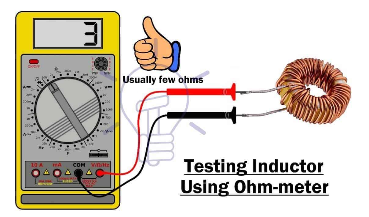
- If the resistance is very low (close to 0), then the inductor has probably short turns.
- If the meter reads very high resistance, the inductor is damaged (open).
Continuity Test For Fuse, Switch, Cables Etc.
We have a detailed article on How To Test Electrical & Electronics Components such as Switches/Push buttons, Fuse, Wire/Cables, batteries, resistor etc with Multimeter?
Homemade Continuity Tester
You can even make a continuity tester yourself at home using a 9v battery, resistor, buzzer or LED and two wires.
The simplest tester can be made as shown in the figure below:

You can also tweak this design by adding switch button for on/off & LED for visual identification.
Related Posts:


its amazing thank u
Good