How to Measure Resistivity of Earth Using Wenner Method?
Wenner 4-Point Method for Testing the Specific Resistance of Soil
What is Wenner 4-Point Test?
The Wenner Method (named after Dr. Frank Wenner of the US Bureau of Standards in 1915), also known as the Four-Point method is a widely used technique for measuring the resistivity (specific resistance “ of the Earth. It plays a crucial role in various fields, such as geophysics, environmental science, civil engineering, and mineral exploration and especially for grounding / earthing systems in electrical installations. This article provides a detailed overview of the Wenner 4-Point Method, explaining its principles, setup, and the steps involved in measuring Earth resistivity.
The resistivity of the Earth is a fundamental property that influences the flow of electric current through its subsurface layers. Understanding Earth resistivity is essential for applications like locating groundwater, assessing soil contamination, and designing grounding systems. The Wenner 4-Point Method offers an accurate and reliable approach to measure resistivity in diverse geological conditions.
Principles of Wenner 4-Point Method:
The Wenner 4-Point Method is based on Ohm’s Law, which relates the electric current (I), voltage (V), and resistance (R) in a circuit. The method involves driving a current through the Earth using four equally spaced electrodes and measuring the potential difference between them.
The key formula used in the Wenner 4-Point Method is:
ρE = 2π.a.RE
Where:
- ρE is the resistivity of the Earth,
- is the electrode spacing,
- RE is the ground/earth resistance
Procedure for Wenner 4-Point Method:
Equipment Setup:
To conduct a Wenner resistivity measurement, a specific setup is required. This typically involves the following components:
- a. Current Electrodes: Four equally spaced electrodes, denoted as C2, P2, P1, and E1.
- b. Potential Electrodes: Located midway between the current electrodes.
- c. Current Source: Provides a controlled current to the electrodes.
- d. Voltage Measurement: Instruments for measuring potential difference.
Process:
- Electrode Placement: Install the four electrodes in a straight line with equal spacing ‘a’. Measure and record the distance between them.
- Current Injection: Apply a known current (I) between electrodes C2 and P2.
- Potential Measurement: Measure the potential difference (V) between electrodes P1 and E1.
- Data Collection: Record the values of current, potential, and electrode spacing.
- Calculation: Use the Wenner formula to calculate Earth resistivity.
Related Post: How to Test the Earth Fault Loop Impedance – Various Methods
How to Measure Ground Resistivity using Ground Resistance Tester?
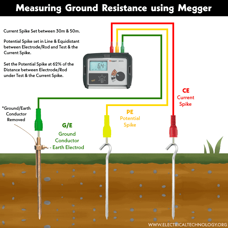
Alternatively, you may use the megger or digital ground-earth resistance tester (e.g., Fluke 1625-2 geo-earth ground tester) for the same setup mentioned above as follows:

Dig and position all four spikes, having the same length, in a line with the distance “a” between them. The earth electrode or ground rod should not be deeper than a maximum of 1/3 of “a.”
- Connect the Ground Rod to the E/C1 Terminal.
- Connect the 1st Potential spike to the ES/P1 terminal.
- Connect the 2nd Potential spike to the S/P2 terminal.
- Connect the Current Spike to the H/C2 terminal.
- Rotate the central rotary switch to position “RE 4POLE.”
- Press the “Start Test” button.
- Observe the reading. The digital display will show a value of ground resistance “RE.”
- Now, use the soil resistivity formula mentioned above to calculate the specific resistance of the earth-ground (or see the following solved example.
Good to know:
- All four ground stakes should be positioned in the soil in a straight line and equidistant from each other.
- The distance between the stakes should be greater than three times the length of the testing ground rods. In other words, the minimum depth of the ground stakes should be one-third (1/3) of the distance between the testing rods.
- For example, if the length of the testing rods is 2.5 m (8.2 ft.), the distance between the ground stakes should be equal to or greater than 7.5 m (24.6 ft.).
Factors Influencing Measurement Accuracy:
Several factors can affect the accuracy of resistivity measurements using the Wenner 4-Point Method, including:
a. Electrode Spacing: Proper selection of electrode spacing is crucial for accurate results. b. Soil Homogeneity: The method assumes uniform soil properties between electrodes. c. Environmental Interference: External factors like temperature and moisture can impact measurements.
How to Calculate Soil Resistivity?
Example:
Calculate the earth resistivity at a depth of 3 m, where the length of the ground rod is 2.5 m (8.2 ft.) and the spacing between electrodes is 7.5 m (24.5 ft.) for your grounding-earthing system.
Solution:
Firstly, connect all the electrodes (spikes) to the desired terminal, as mentioned above in the tutorial, using a digital earth resistance tester. When you press the ‘Test-Measure’ button, suppose the ‘ground resistance – RE‘ indicated by the earth / ground resistance tester is 50 ohms.
Using the soil resistivity formula and inputting the values:
ρE = 2π.a.RE
ρE = 2 × 3.1416 × 7.5 meters × 50 Ω
ρE = 2356.2 Ωm.
The specific resistance (ground resistivity) in this case is 2356.2 Ω⋅m.
Good to know: If you know the value of earth resistivity, you can easily calculate the ground resistance (RE) using the same formula as above
Recommended Value of Earth Resistivity
The recommended earth resistivity or soil resistivity for a good grounding-earthing system can vary based on the standards and guidelines provided by different organizations. Standards such as those from the National Electrical Codes (NEC) Institute of Electrical and Electronics Engineers (IEEE), the International Electrotechnical Commission (IEC), and the British Standards (BS) provide general recommendations for grounding system design. Here are some guidelines from these organizations:
The National Electrical Code (NEC)
NEC does not specify a specific value for earth resistivity or soil resistivity. Instead, it provides guidelines for designing grounding systems based on the characteristics of the soil and the type of installation. The NEC recognizes that soil resistivity can vary significantly in different locations and conditions.
NEC Article 250 provides guidelines for grounding and bonding, including requirements for electrode installation and resistance. It typically requires that the grounding electrode system has a resistance low enough to facilitate the operation of overcurrent devices in the event of a fault.
IEEE (Institute of Electrical and Electronics Engineers):
IEEE Std 80-2013, “Guide for Safety in AC Substation Grounding,” provides guidelines for grounding in high-voltage (HV) substations. It suggests that soil resistivity values for HV substations should ideally be less than 500 ohm-meters for effective grounding. Lower resistivity values are often preferred for critical installations.
IEC (International Electrotechnical Commission):
IEC 60364-4-41:2005, “Low-voltage electrical installations – Part 4-41: Protection for safety – Protection against electric shock,” is an IEC standard that provides guidelines for electrical installations, including grounding. While it does not specify specific soil resistivity values, it emphasizes the importance of achieving low ground resistance for safety.
BS (British Standards):
BS 7430:2011, “Code of practice for protective earthing of electrical installations,” is a British Standard that provides guidance on protective earthing, including soil resistivity. It recommends that the earth resistance of an earthing system should be as low as practicable and that soil resistivity should be measured to ensure an effective grounding system.
It’s important to note that specific requirements may vary based on factors such as the type of installation, local conditions, and the criticality of the system. In many cases, soil resistivity testing is conducted at the site to determine the appropriate grounding design for a specific location.
Consulting the relevant standards and working with a qualified electrical engineer or professional experienced in grounding system design is recommended to ensure compliance with the specific standards applicable to the project.
Applications of Wenner 4-Point Method:
The Wenner 4-Point Method finds extensive applications in various fields:
- Electrical Engineering: Mainly used for ground resistance and earth / soil resistivity for grounding and earthing systems.
- Groundwater Exploration: Assessing subsurface water availability.
- Environmental Studies: Detecting soil contamination and monitoring changes.
- Civil Engineering: Designing efficient grounding systems for structures.
- Mineral Exploration: Mapping mineral deposits in the Earth’s crust.
The Wenner 4-Point Method is a powerful tool for measuring Earth resistivity, offering valuable insights into subsurface conditions. By understanding its principles, setup, and potential challenges, researchers and professionals can make informed decisions in fields ranging from geophysics to civil engineering. This method continues to play a vital role in advancing our understanding of the Earth’s subsurface properties.
Related Posts:
- Electrical Earthing and Grounding – Methods, Types and Installation
- How to Size the Earth Conductor, Earthing Lead & Earth Electrodes?
- How to Test Earthing – Grounding System using a Light Bulb?
- Protective Multiple Earthing (PME) – TN-C-S – (MEN) and PNB
- How to Measure Earth Loop Resistance Using Ammeter and Voltmeter?
- Design of Grounding / Earthing System in a Substation Grid
- Why are Salt and Charcoal Added in Earthing Pit for Grounding?
- What is the Purpose of Ground Wire in Overhead Transmission Lines?
- Difference Between Grounding, Earthing and Bonding
- What is the Difference Between Neutral, Ground and Earth?
- Difference Between Real Ground and Virtual Ground
- Why is the Grounding Wire Bare and Not Insulated?
- Why is Copper Rod Used as Ground Rod in Grounding / Earthing System?


