How to Measure Power using Digital and Analog Multimeter?
Measurement of Electric Power with a Multimeter? (DMM – Analog Meter)
A multimeter is a very essential tool for electrical and electronics engineers, technicians, electricians, students and hobbyists. It can measure multiple quantities such as voltage, current, resistance, capacitance, frequency temperature and continuity, etc. and testing electrical and electronic components such as resistors, capacitors, diodes, transistors and cables and wires etc.
Power is the amount of energy being consumed per unit of time. It shows if a device is consuming too much energy (general term as electricity) or to know a power supply has enough power to run a device without any issue.
Related Posts:
- How to Measure Current using Digital and Analog Multimeter?
- How to Measure Voltage using Digital and Analog Multimeter?
Measuring Electric Power using Multimeter (DMM & Analog AVO meter):
We cannot measure power directly by placing the testing leads on a circuit. However, we can use these readings to calculate electric power using a multimeter to first measure the voltage and current in the circuit.
To do so, we will have to fist measure the Voltage and Current in the circuit using multimeter and then use the power formulas for AC and DC circuits to find the exact value of power in watts.
Measuring Voltage
The first step is measuring the voltage across the component, device, or circuit.
- Switch ON the multimeter.
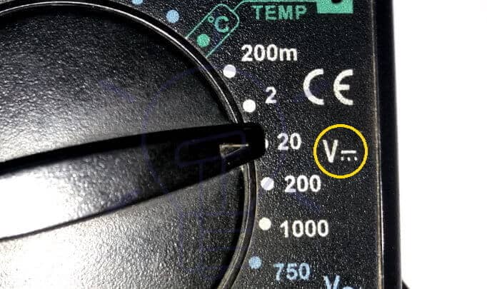
- Turn the Selector knob to the voltage measurement. Ṽ for AC voltage while VDC (or V having a line and dots over it like V ”’) for DC voltage.
- Select voltage range a little higher than the expected range or choose the highest range if the voltage is unknown.
- Place the black probe in the COM socket and the red probe in the V socket.
- Place the leads across the device, black lead over low voltage point and the red lead over high voltage point.
- If possible, reduce the range to get an accurate reading.
- Note the voltage readings and remove the probes.


Note: DC voltage has a polarity, keep the polarity in consideration while measuring with an analog multimeter. There will be no deflection while a digital multimeter only shows a negative sign with the actual reading. For DC Voltage measurement, there is DC symbol printed on the meter e. g. VDC = V ”’.

Related Posts:
- How to Measure Resistance using Digital & Analog Multimeter?
- How to Check a Capacitor with Digital (Multimeter) and Analog (AVO Meter)
Measuring Current
The second step is measuring the current flowing through the component, device, or circuit.
- Switch OFF the power supplied to the circuit
- Switch ON the multimeter.
- Turn the Selector knob to the current measurement. Ã denotes AC current and
“A” with a line and dots denotes DC current e.g A ”’.. - Select suitable current range higher than the expected if unsure use maximum range.
- Place the black probe in the COM socket and the red probe in the A socket (use proper socket based on the selected range. low current “mA” and high current “A”).
- Break the circuit at a convenient point and place the meter in series with it.
- Connect the black lead and the red lead firmly with the circuit to make a complete circuit.
- Switch on the power supply to the circuit.
- If possible, reduce the range to get an accurate reading.
- Note the current readings and remove the probes.


Note: DC current has polarity. Polarity must be considered while measuring with an Analog multimeter. For DC Current measurement, there is DC symbol printed on the meter e. g. ADC = A ”’.
Related Posts:
- How to Perform the Continuity Test with Multimeter?
- How to Test a Relay? Checking SSR and Coil Relays
Clamp Meter
A clamp meter can be used to measure current in a line without any physical contact. it is a safe and quicker way to measure current in high voltage circuits. It is easier to use and does not require you to break or switch off the power supply to the circuit.
Some multimeters have a built-in clamp meter. However, current clamp probes are also available that can be used with a normal multimeter. Current clamp probes convert the current into a voltage that is proportional to the current reading.
- Switch ON the multimeter
- Turn the selector knob to the current measurement.
- Select a suitable range.
- Clamp the meter to a single line.
- Adjust the range for an accurate reading.
- Note the reading of the meter.
If you are using current clamp probes using a normal multimeter, then follow these steps to measure current.
- Switch ON the multimeter.
- Turn the selector knob to voltage measurement (AC voltage for AC current and DC voltage for DC measurement) because the clamp probe converts the current into voltage.
- Select a suitable range based on the clamp probe conversion ratio.
- Connect the black and red probes of the clamp probes into the COM and Voltage socket of the multimeter.
- Clamp the probe to the line.
- Note the voltage reading in the meter.
- Convert this voltage into current using the current conversion ratio of the current clamp probe.
For example, A clamp probe has a conversion ratio of 1mV/A and the voltage readings show 5 mV. Then the current measurement is 5 Amperes.
Related Posts:
Calculate the Power in Watts using Formulas
Measuring Power in DC Circuits:
We can use the basic formula to calculate power based on the readings we just had. This formula works for both DC circuits and AC single phase circuits having pure resistive load.
Power = Voltage x Current
P = V x I
Power is the product of voltage and current. We just simply need to multiply both readings together to get the power consumed by the component.
For example, we have 220 volts across a device that draws a current of 5 Amps through it. Then the power consumed would be:
Power = Voltage x Current
Power = 220 volts x 5 Amps
Power = 1100 watts or 1.1 Kilowatts
Similarly, If the measured voltage in the circuit is 110V AC and the the value of current is 15A, the total consumed power would have:
Power = 110 V x 15 A
Power = 1650 Watts or 1.65 kW
In case of battery, if the measured voltage is 12V and the drawn amperage is 6A. The power drawn by the battery is:
Power = 12VDC x 6 A
Power = 72 Watts.
Since the battery is rated in Ah, we only measured the wattage capacity of the battery. Not the ampere hour rating.
Related Posts:
- How to Test a Diode using Digital and Analog Multimeter
- How to Check a Transistor by Multimeter (DMM+AVO)
Measuring Power in AC Circuits:
Measurement of electric power in AC circuits is a little bit complex due the role of power factor and poly phase systems (generally single phase and three phase)
In case of capacitive and inductive load circuits (motors etc), you will have to calculate the power factor (where power factor = Cosθ = R/Z or W/VA) to find the exact value of power in wattage.
If you know the value of P.F, you may use the following electric formulas to calculate the power in wattage in AC circuits.
Power in Single Phase AC Circuits
P = V x I x Cosθ
Power in Three Phase AC Circuits:
P = √3 x VL-L x I x Cosθ
P = 3 x VL-N x I x Cosθ
Points to be Noted while Making the Measurements:
- Beware of the AC current of the mains. It can electrocute a person. Be cautious when working with high voltages.
- Do not touch the tip of the probes while there is power supplied to the circuit. Even if one probe is connected it can still shock you.
- Touching the tip of the probes also inflicts error in the readings (especially in low voltage current measurement).
- AC current has no polarity, swapping the probes will not affect the readings. However, DC has polarity and it must be considered especially in analog meters.
- Do not let the probes connect with each other.
- Be very careful of using the correct socket for measuring current and voltage.
- Voltage is measured by connecting the meter in parallel and the current in series.
- Do not connect the meter in parallel to the circuit while measuring the current. it will damage the meter unless there is a fuse (that will definitely blow).
Related Multimeter Tutorials:
- How to Test Electrical and Electronics Components and Devices with Multimeter
- Basic Electrical and Electronics Engineering Tools
- How to Find The Suitable Size of Cable and Wire for Electrical Wiring Installation?
- How to Find the Proper Size Outlets, Receptacle and Switch?
- How to Find the Right size of circuit breakers?
- How to Calculate the Value of Resistor for LED’s?
- How to Calculate the Battery Charging Time and Charging Current? Example
- How to Find the Proper size of Earth Conductor, Earth Lead and Earth Electrodes?
- Resistor Color Code Calculator – 3, 4, 5 & 6 Band Resistors Calculation
- How to Find The value of Burnt Resistor? (4 Methods)


Thanks for easy tutorial.