How to Measure Resistance using Digital & Analog Multimeter?
Measuring Resistance with a Multimeter? (DMM – Analog Meter)
Measuring resistance just like voltage and current is an important part of troubleshooting any component. It tells the condition of the components. The resistance measurement is also used to check for open or closed circuits. Last but not least you can check how accurate the resistors are since they are also color-coded.
Related Posts:
- How to Measure Resistance using Digital & Analog Multimeter?
- How to Measure Voltage using Digital and Analog Multimeter?
What is Resistance?
Resistance is the opposition to the flow of current. The device that is used for measuring the resistance is called Ohmmeter. Ohmmeter has a voltage across its both terminals that flow the current through the component being tested. If the resistance is very high it means the low current will flow. If the resistance is low it means the current flowing will be high. Based on the amount of current flowing, it determines the resistance.
We can also utilize the resistance readings to determine a short circuit or a broken circuit. In this multimeter tutorial, we will measure the resistance using DMM and analog multimeter with step by step guide. Before you go to follow the steps, you may know the basic difference between AC and DC resistance.
Related Posts:
- How to Check a Capacitor with Digital (Multimeter) and Analog (AVO Meter)
- How to Test a Diode using Digital and Analog Multimeter
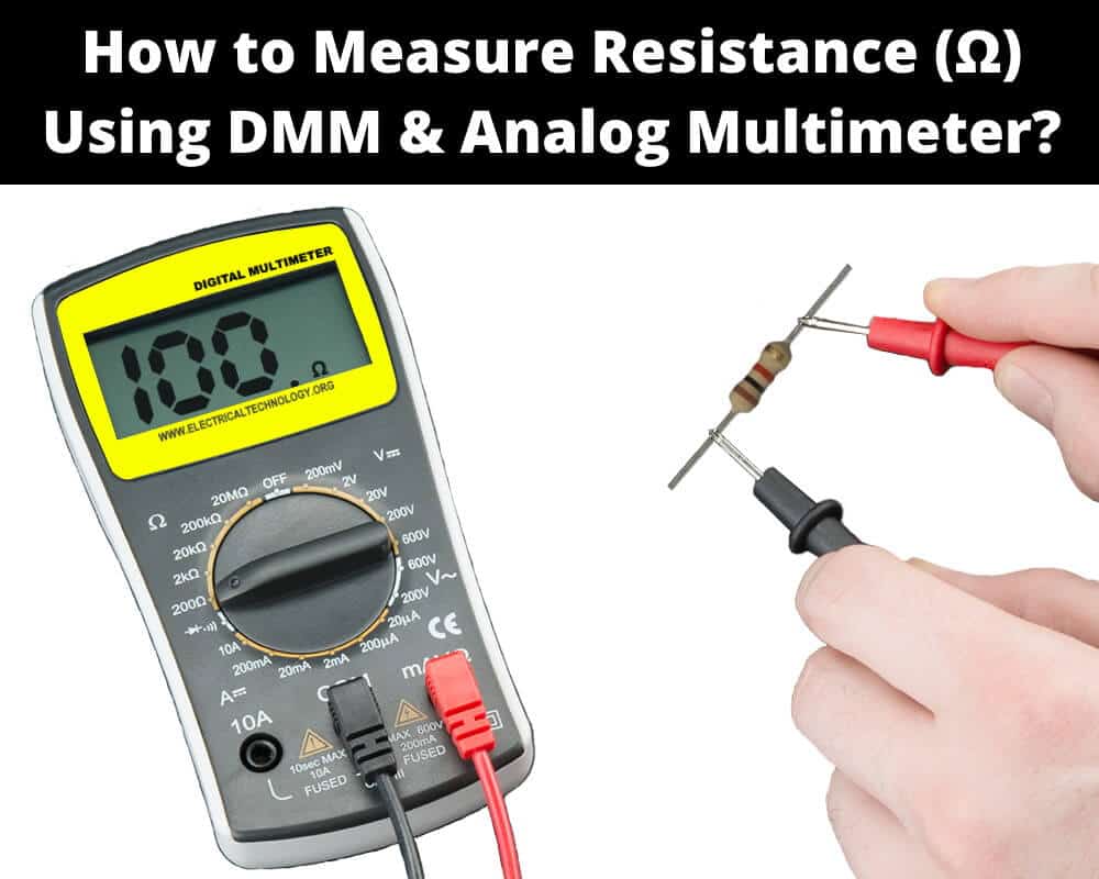
Measuring Resistance using Digital Multimeter:
- Switch off the power supply to the circuit.
- If there is a capacitor on board, discharge it first.
- Isolate the component whose resistance needs to be measured. If possible remove it from the circuit to avoid any parallel paths that may interfere with the total resistance.
- Switch ON the multimeter.
- Turn the selector knob to the resistance Ω

- Select a suitable range slightly higher than the expected resistance reading for high accuracy. If it is unknown, select the higher settings. It can be brought back down later.

- Insert the black probe in the COM (common) socket.
- Insert the red probe in the Ω Most DMMs have a shared socket used for Ω, V and continuity. Use the socket that has Ω symbol on it.

- Connect the leads across the component.
- Note the reading. Change the range to the lowest possible setting to get an accurate reading.
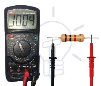 The given 1K Ohm resistor’s measurement shows 1004 Ohm resistance which is more accurate as the 4th color band (gold) shows tolerance of 5%
- When finished, remove the probes and turn the selector knob into the voltage mode to prevent damage by accidentally connecting to high voltage.
Note: Do not measure the resistance of a circuit with power still ON. Look out for capacitors in a circuit before testing a component. The components in parallel also affects the equivalent resistance. make sure the component being tested does not have any other component in parallel. Do not touch the tip of the leads while measuring, it will inflict error in the reading.
Related Posts:
- How to Check a Transistor by Multimeter (DMM+AVO)
- How to Perform the Continuity Test with Multimeter?
Measuring Resistance using Analog Multimeter:
Analog multimeter has the same procedure. However, it has a little calibration to perform while measuring resistance.
- As usual, switch off the power supply to the circuit first and discharge if there is any capacitor.
- The component being tested must not have any component in parallel. If possible, remove the component from the circuit.
- Switch ON the Analog multimeter.
- Turn the selector knob to the resistance Ω

- Select a suitable range slightly higher than the expected resistance reading for high accuracy. It can be changed back later.

Note: The analog multimeter resistance range has multiplying factors. For example, x1, x10 and x100 are different ranges showing the scale value multiplying by the factor to get the actual reading.
- Insert the black probe in the COM (common) socket.
- Insert the red probe in the Ω Some meters share the Ω socket with voltage. Use the socket having the Ω symbol on it.

- Calibrate or adjust the zero of the meter by connecting both probes together and rotating the zero adjustment knob to show full-scale deflection i.e. 0 ohms.

- Connect the leads across the component.
- Note the reading. Adjust the range of the meter to show maximum possible deflection to get maximum accuracy.
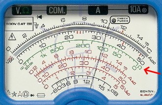
- If the range is x1, then this reading is 100 ohms. If the range x10, the reading is 1000 ohms. If the range is x100, the reading is 10,000 ohms.
- After finishing, remove the probes and select the voltage measurement mode to avoid accidently connecting it to voltage.
Related Posts:
Factor Affecting Resistance Readings
The resistance can be affected by many factors. Therefore, while measuring resistance the following factors must be considered:
Component in a circuit: If the component is inside a circuit, its resistance can be affected by any other components in parallel.
Power through the circuit: if there is power supplied to the circuit or any charged capacitor, it will affect the readings since the ohmmeter works on the basis of current flowing through the meter.
Diode in a circuit: If there is a diode in a circuit, the resistance of the circuit will vary if the probes are swapped with each other. it is due to the fact that the diode does not allow current in one direction.
Fingers touching the leads: if your fingers are touching the leads, it will affect the reading due to the leakage of some current through your body. Do not touch the tip of the leads while measuring resistance.
Temperature: Most component’s temperature rise when current passes through them. It is best not to measure the resistance when they are hot because the temperature affects the resistance.
Related Posts:
- How to Test and Fix the Printed Circuit Board (PCB) Defects?
- Why is Zero Ohm Resistor Used? 0-Ω Resistor Applications
Powered ON Circuit
Always make sure there is no power supplied to the circuit. it not only affects the readings of the resistance but also the high voltage will damage the multimeter as well.
Relative, Zero or Delta Mode
Modern DMM has “REL” mode short for relative mode which is also known as zero or delta mode. It is used for measuring very small resistance. In this mode, the resistance of the probes is automatically subtracted from the reading. When the probes are shorted together, it should show 0 ohms.
Zero Adjustment of Analog Multimeter
The zero calibration or zero adjustments is a very important step before measuring resistance using an analog multimeter. When the probe leads are shorted together, it should provide full-scale deflection (FSD) meaning zero ohm resistance between the leads.
If there is no FSD i.e. it shows some resistance, it must be eliminated by turning the zero control knob to move the needle go all the way to FSD.
It is also affected by varying the range of the meter. Therefore, whenever you change the range of the meter, zero calibration must be performed.
If you are unable to get FSD even after connecting the probes together and turning the zero control, the multimeter battery is depleted and needs to be replaced.
Battery Depletion
Unlike voltage and current measurement, the resistance measurement consumes the battery inside the meter. Therefore, if the battery is depleted, it will affect the reading. The DMM show clear indications for low battery and it will also show high resistance between its probes. However, an analog multimeter does not have such indications. Instead, if it does not show FSD when connecting the probes together, the battery is low and must be replaced.
Related Multimeter Tutorials:
- How to Test Electrical and Electronics Components and Devices with Multimeter
- Basic Electrical and Electronics Engineering Tools
- How to Find The Suitable Size of Cable and Wire for Electrical Wiring Installation?
- How to Find the Proper Size Outlets, Receptacle and Switch?
- How to Find the Right size of circuit breakers?
- How to Calculate the Value of Resistor for LED’s?
- How to Calculate the Battery Charging Time and Charging Current? Example
- How to Find the Proper size of Earth Conductor, Earth Lead and Earth Electrodes?
- Resistor Color Code Calculator – 3, 4, 5 & 6 Band Resistors Calculation
- How to Find The value of Burnt Resistor? (4 Methods)


