How to Measure Capacitance using a Multimeter?
Measurement of Capacitance with a Digital Multimeter
To accurately measure the capacitance of a capacitor, you require expensive instruments such as an LCR meter which can measure Inductance (L), Capacitance (C) and resistance (R) accurately while keeping various parameters such as frequency into account. A digital multimeter (DMM) can also measure capacitance with some precision but their range is very low.
Capacitance
Capacitance is the ability of a capacitor to store energy in the form of an electrical charge. It stores it between two conducting plates separated by a dielectric film.
It is measure in Farad. One farad capacitance is equal to one coulomb of the charge stored in a capacitor when one volt of potential difference is applied. One farad is a very large unit. Therefore, capacitance is usually measured in microfarad (μF) and millifarad (mF).
Related Post: How to Test a Capacitor using Digital and Analog Multimeter – 6 Methods
Working Principle
A multimeter measures the capacitance by charging the capacitor with a known current. It basically measures the rate of rising of the voltage across the capacitor. The rate of voltage is inversely proportional to the capacitance.
IC = C dV/dt
Where
- IC = Capacitor current (Known current supplied by meter)
- C = Capacitance
- dV/dt = Rate of voltage change
If the voltage rise is slow, the capacitance is large and vice versa. DMMs do not support a wider range of capacitance measurements.
Caution
Capacitors store charge even after removing the power supply. It is important to discharge a capacitor before touching it or connecting it to a meter. First of all, remove the power supply connected to the circuit. To safely discharge the capacitor, connect a resistor across its terminals. A decent capacitor has enough charge to shock a person and it may damage a meter by discharging through its internal circuit.
Related Posts:
- How to Measure Current using Digital and Analog Multimeter?
- How to Measure Voltage using Digital and Analog Multimeter?
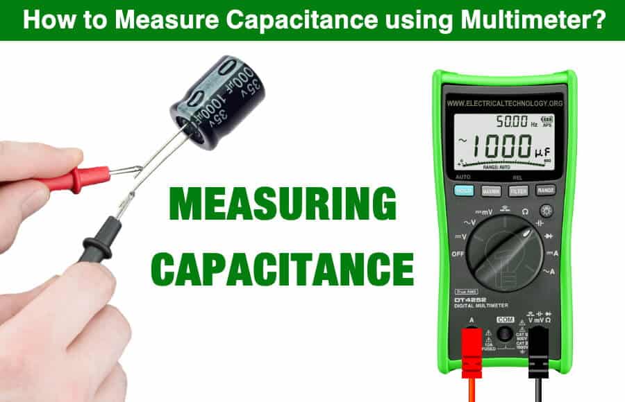
Measuring Capacitance
Capacitance can be measured with inexpensive digital multimeters having capacitance “-|(-” or “F” measurement. it can provide a rough reading that is not very precise. For accurate measurement, LCR meter is used which is very expensive and they can even measure the capacitance when the capacitor is on board by using ESR (Equivalent Series Resistance)
As you know that using a digital or analog multimeter, we can measure multiple electrical quantities such as voltage, current, resistance, capacitance, frequency temperature and continuity, etc and testing electrical and electronic components such as resistors, capacitors, diodes, transistors and cables & wires etc. In the following multimeter tutorial, we will show how to measure the exact value of capacitance of a capacitor using a DMM.
Method 1:
Here is a step by step guide for capacitance measurement using a digital multimeter
- First of all, switch off the power supplied to the circuit. Ensure the power is off by measuring the voltage across it. It should read 0 volts.
- Do a visual inspection of the capacitor. A faulty capacitor may have leak, bulge, and crack. Replace if it is faulty or follow the next step.
- Safely discharge the capacitor by connecting a resistor across its terminal. Use proper resistor (5watt resistor) for safe discharge.

- If the capacitor is in a circuit, carefully remove it by any means. It gives inaccurate readings while in a circuit due to other parallel components.

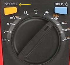
- Turn the dial to the capacitance symbol “-|(-” or “F”. Press the “shift” button to activate the secondary function if it shares the spot with another function.

- Select approximate range settings from the dial. Some DMMs have an auto-range feature.
- Insert the black probe into the “COM” port and the red probe into the correct red port marked with “-|(-”.

Note: Some DMMs have dedicated ports for placing the capacitor as shown in the figure below.

- Press the “REL” button (if your meter has it). It will subtract the capacitance of the test leads. It helps in proving precise and accurate reading for small capacitance.
- Connect the black lead to the negative (-) and red lead to the positive (+) leg of the capacitor.
A non-polar capacitor does not have polarities. A polar capacitor has some identification of negative and positive terminal such as “a – marked strip near the negative terminal” or “the longer leg is the positive terminal”.
- The meter will start to charge the capacitor. Therefore, wait for the reading on the display to become stable. If it shows “OL”, increase the range of the meter.
- If it still shows “OL”, the capacitance is out of range of the meter or the capacitor is faulty.
- When the measurement is finished, remove the red probes first and then the black probe.
- Switch the multimeter off or turn the dial to the voltage measurement.
Related Posts:
- How to Measure Resistance using Digital & Analog Multimeter?
- How to Measure Frequency using Multimeter?
Method 2:
To do this, you will need a battery (lower than the voltage rating of the desired capacitor), a known value of resistor (such as10kΩ) and a stopwatch and a multimeter. Generally, the voltage rating is printed on the capacitor nameplate. We will charge the capacitor about 63.2% of the supply voltage and note the reading.
To do so, follow the following steps
- Disconnect and fully discharge the capacitor
- Connect a 10kΩ in series with the battery and capacitor positive terminals.
- Connect the 9V battery and multimeter to the capacitor for charging and start the stopwatch.
- When the multimeter shows a 5.7V, Stop the watch and note the reading in second.
- Now follow the following example to know the value of capacitance.

For example, We have a 16V, 470μF rated capacitor. if the supply voltage is 9V, then 63.2% of the supply voltage is around 5.7V. We will start to charge the capacitor and start the stopwatch as well. When the multimeter shows the 5.7V, We will stop the stopwatch and note the time in seconds. Suppose, the time was 4.7 seconds.
Now, Apply the time constant formula to calculate the value of capacitance.
τ = RC
C = τ / R
Where: C is capacitance, R is resistance in ohms and τ is the time in seconds.
Putting the values
- C = τ / R
- C = 4.7 s / 10000Ω
- C = 4.7 s / 10000Ω
- C = 0.00047
- C = 47mF
- C = 470μF
Important Points
- Do not touch the tip of test leads while measuring capacitance. It may inflict errors in the reading.
- Some multimeters do not use test leads to measure the capacitance. They have special ports for it.
- Do not short the terminals to discharge a capacitor. It may damage the capacitor. Use a resistor.
- Do not forget about the polarity of polarized capacitors.
- Do not measure capacitance while the capacitor is connected in a circuit. Although, an LCR meter can be used to measure capacitance while in a circuit.
- The Analog multimeter does not have a power source to supply a constant current. Therefore, it cannot measure capacitance. However, it can be used to test a capacitor.
- If it has cracks, bulges, or leaks. Do not charge it, it might explode as it is faulty.
- A digital multimeter cannot provide precise measurement but they give a rough reading.
- Use “REL” mode for very small capacitance to get a more accurate reading.
- An LCR meter is used for precise and accurate capacitance measurement.
Related Posts:
- How to Perform the Continuity Test with Multimeter?
- How to Test a Relay? Checking SSR and Coil Relays?
Importance of Capacitance Measurement
The capacitors have a limited life span and their capacitance decreases with continuous use. It can affect the operation of the components in the system and in an extreme case, it may explode.
- The capacitance measurement tells us about the capacitor’s actual health.
- It tells if the capacitor is faulty. A faulty capacitor may be short, open, or have lower capacitance than expected.
- Capacitors have their value marked on them. They should be checked if the value falls in its range. If not, they are faulty.
- A faulty capacitor can cause a malfunction in the system.
- A short capacitor can blow other components if not protected by a fuse.
- An open capacitor can stop the supply to other components.
- A capacitor-start motor cannot start due to a faulty capacitor.
- A single-phase motor may get slower and noisy due to a faulty capacitor.
- A power correction unit cannot work properly if one of the capacitor’s capacitance deteriorates.
- A physically deteriorate capacitor can explode.
Note: This post has been published by www.electricaltechnology.org
Related Tutorials
- Capacitor Code: How to Find the value of Ceramic Capacitors?
- How to test a battery with Test meter?
- How to Test and Fix the Printed Circuit Board (PCB) Defects?
- How to Test a Diode using Digital and Analog Multimeter
- How to Check a Transistor by Multimeter (DMM+AVO)
- How to Test Electrical and Electronics Components and Devices with Multimeter
- Basic Electrical and Electronics Engineering Tools
- How to Find The Suitable Size of Cable and Wire for Electrical Wiring Installation?
- How to Find the Proper Size Outlets, Receptacle and Switch?
- How to Find the Right size of circuit breakers?
- How to Calculate the Value of Resistor for LED’s?
- How to Calculate the Battery Charging Time and Charging Current? Example
- How to Find the Proper size of Earth Conductor, Earth Lead and Earth Electrodes?
- Resistor Color Code Calculator – 3, 4, 5 & 6 Band Resistors Calculation
- How to Find The value of Burnt Resistor? (4 Methods)


