What is a Main Bonding Jumper – Sizing MBJ and Where Can It Be Found in an Electric Panel?
Main Bonding Jumper (MBJ)
In an electrical panel or load center, the Main Bonding Jumper (MBJ) is the conductive connection that bonds (connects) the grounded conductor (neutral) to the equipment grounding conductor and the metal enclosure of the panel.
This connection ensures that the neutral busbar and the grounding system are electrically tied together at the service disconnect, which creates an effective fault-current path.
Definition:
The Main Bonding Jumper (MBJ) is a screw, strap, or conductor that connects the neutral busbar to the metal enclosure (panel cabinet) and grounding busbar at the main service equipment (service disconnecting means).
According to NEC Article – 100, a Main Bonding Jumper is the connection between the grounded conductor (neutral), and the equipment grounding conductor, and the service disconnect enclosure.
A bonding jumper (bonding conductor) is used for electrical connectivity between the metallic bodies of two equipment. This process is known as electrical bonding.
Good to Know:
- Equipment Bonding jumper: is the connection between two or more portions of the equipment grounding conductor
- System Bonding Jumper: is the connection that bonds the grounded conductor of a separately derived system to the equipment grounding conductor
- Supply Side Bonding Jumper: is the connection between metal parts required to be electrically connected installed on the supply side within a service equipment enclosure(s).
Purpose of the Main Bonding Jumper
The MBJ performs several important safety functions:
It creates a fault current path to allow ground-fault current to return to the source so the circuit breaker trips quickly. It bonds metal parts together i.e. the panel enclosure, neutral conductor, and grounding conductors are connected at one point.
MBJ helps to establishes the neutral conductor at earth potential and eliminates the risks associated with the faults current. Without the bonding jumper, fault current may not be high enough to trip the breaker.
Thank to the main bonding jumper, that’s why you can safely touch the metal enclosures and panel box without being electrically shocked.
Good to Know: Don’t confuse between Main bonding and main bonding jumper in a panel. The main bonding is a connection using metal strap between ground and neutral busbars in the main panel. The main bonding jumper is used to electrically connect the metallic body of electric panel to the grounded circuit (ground busbar).
Where the Main Bonding Jumper is Located
In a main service panel, the grounded terminal bar (neutral busbar) is connected to all grounding wires, i.e. equipment grounding conductors (EGCs), the grounding electrode conductor (GEC) i.e. the wire that runs between the ground rod and the neutral/ground busbar, and the metallic enclosure of the panel through the main bonding jumper.
- In modern panels and load centers, a green bonding screw is often located right above (or beside) the neutral terminal bar.
- In some panels, a short strap or wire is also used to bond the panel box to the insulated neutral terminal bar.
The MBJ is installed only in the main service equipment, such as:
- Main breaker panel
- Main service disconnect
- Meter-main combination panel
It is not installed in subpanels.
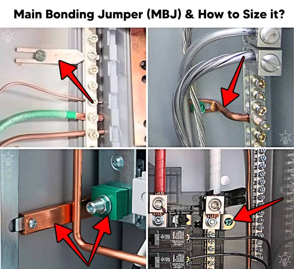
Typical forms of MBJ in an electric panel (as shown in the following fig) include:
- Green bonding screw
- Bonding strap
- Bonding jumper wire
Good to Know:
- The neutral and ground must be bonded at only one point in the electrical system, which is the main service disconnect e.g. main panel. In other words, the neutral and ground must be separated in a subpanel.
- In subpanels, neutral busbar should be isolated from the panel cabinet while the ground busbar should be bonded to the cabinet.
- Main bonding jumper is available in both main panels, and service/subpanels. However, the main bonding or connector bar between ground and neutral terminal bars should be removed in case of subpanels. This is because the neutral and equipment grounding conductors in a subpanel must remain isolated from each other.
Sizing Main Bonding Jumper
The size of the Main Bonding Jumper is based on the largest ungrounded service-entrance conductor or the equivalent area for parallel conductors. The Main Bonding Jumper (MBJ) must be sized according to NEC 250.28(D) and Table 250.102(C)(1) as follows:
Example:
What is the suitable size of main bonding jumper for a 120/240V single-phase main panel installation having 3/0 AWG copper service entrance conductors.
Solution:
Identify the largest ungrounded conductor (hot or live wire). In our case, the largest service conductor is 3/0 AWG copper.
Now, refer to the NEC Table 250.102(C)(1) which shows the minimum required size of MBJ is 4 AWG copper for 1/0 – 3/0 AWG copper as largest ungrounded conductor.
Therefore, the minimum Main Bonding Jumper size = 4 AWG Copper
Similarly, the size of MBJ for a 350–600 kcmil copper as a hot conductor in the panel is 1/0 AWG copper.
MBJ Sizing Table
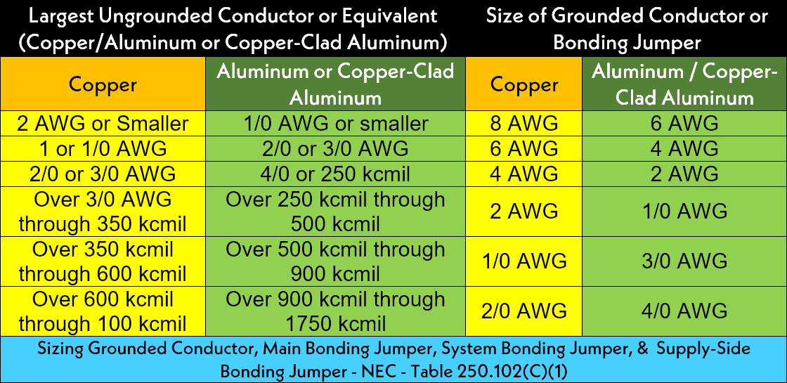
The MBJ can be sized based on largest ungrounded conductor (not the breaker rating) and the values are given in NEC – Table 250.102(C)(1).
| Largest Ungrounded Conductor or Equivalent (Copper/Aluminum or Copper-Clad Aluminum) | Size of Grounded Conductor or Bonding Jumper | ||
| Copper | Aluminum or Copper-Clad Aluminum | Copper | Aluminum / Copper-Clad Aluminum |
| 2 AWG or Smaller | 1/0 AWG or smaller | 8 AWG | 6 AWG |
| 1 or 1/0 AWG | 2/0 or 3/0 AWG | 6 AWG | 4 AWG |
| 2/0 or 3/0 AWG | 4/0 or 250 kcmil | 4 AWG | 2 AWG |
| Over 3/0 AWG through 350 kcmil | Over 250 kcmil through 500 kcmil | 2 AWG | 1/0 AWG |
| Over 350 kcmil through 600 kcmil | Over 500 kcmil through 900 kcmil | 1/0 AWG | 3/0 AWG |
| Over 600 kcmil through 100 kcmil | Over 900 kcmil through 1750 kcmil | 2/0 AWG | 4/0 AWG |
| Sizing Grounded Conductor, Main Bonding Jumper, System Bonding Jumper, & Supply-Side Bonding Jumper – NEC – Table 250.102(C)(1). | |||
Here is the MBJ sizing table in the image format for reference.
NEC Requirements for Main Bonding Jumper
- Each switchboard, switchgear, or panelboard, when used as service equipment, must be provided with a main bonding jumper (MBJ). The MBJ must be sized in accordance with NEC 250.28(D) and based on Table 250.102(C)(1) and Table 250.122, as applicable. This requirement applies except for high-impedance grounded neutral systems installed in accordance with NEC 250.36. (NEC 408.3(C), 409.108, and 430.95)
- If a wire or busbar is used as the main bonding jumper to connect the grounded conductor (neutral) terminal busbar to the equipment grounding terminal (ground busbar) in the service equipment (panel or load center), the grounding electrode conductor (GEC) is permitted to be connected to the equipment grounding terminal busbar to which the main bonding jumper is connected. NEC 250.24(A)(4).
- For each service disconnect, an unspliced main bonding jumper must be used to connect the equipment grounding conductor(s) (EGCs) and the service-disconnect enclosure to the grounded conductor (neutral) within the enclosure. This connection must comply with 250.28, 250.36, and 250.187. NEC 250.24(A)(4)(C) & D.
- A Main Bonding Jumper (MBJ) or System Bonding Jumper (SBJ) made of copper, aluminum, or copper-clad aluminum must be installed in the service equipment. It may be installed in the form of a screw, strap, busbar, or wire-type jumper. NEC 250.28(A).
- If a screw-type bonding jumper is used as the main or system bonding jumper, it must have a green finish for identification. NEC 250.28(B).
- The MBJ must connect the grounded conductor (neutral) to the service disconnect enclosure using an approved bonding method in accordance with NEC 250.8. NEC 250.28(C).
- The Main Bonding Jumper must be sized in accordance with NEC 250.28(D)(1) through (D)(3). The size of the MBJ must not be smaller than the values specified in Table 250.102(C)(1). NEC 250.28(D).
- If a service or separately derived system includes multiple enclosures, the MBJ must be sized based on the largest ungrounded service (Hot) conductor supplying that enclosure, in accordance with NEC 250.28(D)(1). NEC – 250.28(2) & (3).
- The main bonding jumper or system bonding jumper is not required for the normal power source and feeder conductors supplying transfer equipment that will be grounded as a separately derived system, provided the system is installed in accordance with NEC 708.10(C) and 708.11(B). (NEC 708.20(C) – Exception Note).
Precautions:
- Always disconnect the power supply by switching OFF the circuit breaker at the main service panel before performing any electrical work.
- Electrical equipment must be installed according to manufacturer instructions as required by the NFPA and NEC 110.3(B)).
- Never touch the terminal screws above the main breaker. These terminals are always energized and remain live even when the main breaker is switched OFF.
- If you are unsure about any part of the installation, consult a licensed electrician and ensure compliance with applicable local electrical codes.
Disclaimer: Electrical work is dangerous. The author assumes no responsibility for any loss, injury, or damage resulting from the use or misuse of this information, including improper circuit installation.
Resources:
Related Posts:
- National Electrical Code (NEC) Requirements for Panelboards
- What is Double Tapped Breaker and Double Lug in Main Panel
- Busbar, Bus Stab, Breaker Slot and Circuit Space in a Panel
- What Happens if the Neutral is Lost in the Main or Subpanel?
- Why Must Neutral and Ground Wires Be Bonded in the Main Panel?
- Why are Neutral and Ground Wires Separated in a Subpanel?
- Should GFCI Protection Be in the Main Panel or Receptacle?
- Difference Between 1-Pole and 2-Pole Breakers – NEC & IEC
- Difference Between EGC and GEC in Electrical Grounding
- Difference Between Grounding, Earthing and Bonding
- Difference Between Neutral, Ground and Earth?
- Can the Neutral Wire Cause Electric Shock? Different Cases
- Will I Get an Electric Shock If I Touch the Ground Wire?
- Will a Man Get an Electric Shock If He Hangs on a Live Wire?
- What Happens When You Touch an Electrical Busbar?
- Can I Use a 240V Breaker on a 120V Circuit and Vice Versa?
- Can You Use 15A Breaker on 20A Circuit and Vice Versa?
- Why Doesn’t a Standard Breaker Protract Against Ground Faults?
Sizing & Rating
- How to Size a Load Center, Panelboards and Distribution Board?
- How to Determine the Right Size Capacity of a Subpanel?
- How to Size a Circuit Breaker? Breaker Size Calculator
- How to Determine the Number of Circuit Breakers in a Panel Board?
- How to Find the Right Wire Size for 100A Service 120V/240V Panel?
- What is the Correct Wire Size for 100A Breaker and Load?
- How to Find the Number of Lights on a Single Circuit Breaker?
- How to Size a Breaker and Wires in AWG with EGC for Load?
- How to Size a Branch Circuit Conductors with Protection?
- How to Size Feeder Conductors with Overcurrent Protection
- How to Size Service-Entrance Conductors and Feeder Cables?
- How to Size Equipment Grounding Conductor (EGC)?
- How to Size Grounding Electrode Conductor (GEC)?
- How to Find the Proper Size of Wire & Cable In Metric & Imperial Systems
Wiring Tutorials
- How to Wire 120V & 240V Main Panel? Breaker Box Installation
- How to Wire a Subpanel? Main Lug Installation for 120V/240V
- How to Wire 120V & 208V – 1 & 3-Phase Main Panel? 3-Φ Load Center Wiring
- How to Wire a GFCI Circuit Breaker? 1, 2, 3 4 Poles GFCIs Wiring
- How to wire a GFCI Outlet? GFCI Wiring Circuit Diagrams
- How to Wire an AFCI Combo Switch – AFCI Switch Wiring Diagrams
- How to Wire a Single-Pole Circuit Breaker in a 120/240V Panel
- How to Wire a Two-Pole Circuit Breaker in a 120/240V Panel
-
 How to Install a Wireless Smart Scene Switch
-
 How to Wire Smart Scene Controller Switch
-
 How to Install a Home and Away Wireless Smart Switch
-
 Arkansas School Uses Rooftop Solar to Raise Teacher Pay
-
 How to Install a Wire-Free Smart Dimmer Anywhere Companion
-
 How to Wire a Smart Wireless Switch and Anywhere Companion