How to Wire an AFCI Combo Switch – AFCI Switch Wiring Diagrams
AFCI Combo Switch Wiring Circuit Diagrams and Installation
Arc fault circuit interrupter “AFCI” is a protection device used to protect the circuit from electric arcing which cases electric fire. It detects the arc and disconnect the circuit from main power supply.
In our previous posts, we have learned different types of AFCI wiring diagrams such as AFCI circuit breaker, AFCI outlet. In today post, we will show the different wiring diagrams for AFCI combination switch with outlets, light switches and other components and devices to protect the residential areas from unintentional arc fires. Keep in mind that according to NEC 2014, AFCI is must to install in almost all new structures and bedrooms, living rooms etc.
What is an AFCI Combo Switch and How to Wire It?
It is the combination of AFCI with single pole (SPST = Single Pole Single Through) switch. The wiring diagram for AFCI switch is same as GFCI combo switch and outlet.
AFCI switches are used in new circuits or to modify the existing circuits where the switch is the first outlet in a branch circuit. There are two bulletin wires on the back side of AFCI to control and protect the load through the switch in it.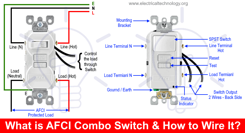
In the following wiring diagrams, we will show how wire and install an AFCI combination switch in an existing or new branch circuits. Moreover, you may read the key difference between GFCI and AFCI in the previous post.
Wiring an AFCI Switch with a Light Bulb
Any load connected to the load terminal of AFCI is AFCI protected. Keep in mind that those loads are not AFCI protected which are connected to the Line terminals of AFCI same like in GFCI wiring diagrams.
In this wiring diagram, one of the builtin wire has been connected to the load terminal of AFCI and the second one (as hot) to the light bulb. The line supply connected to the line terminals while the load neutral is connected to the lighting point hence, light bulb is controlled by the builtin switch and protected by AFCI.
- Related Post: How to Wire Combo Switch and Outlet?

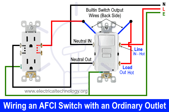
Wiring an AFCI Combination Switch with an Ordinary Outlet / Receptacle
Same like the above wiring diagram, a standard outlet receptacle has been connected to the load terminals of AFCI switch. In other words, the ordinary outlet and any load connected to it is AFCI protected. In addition, the ordinarily outlet can be ON/OFF through the AFCI switch as well as it is controlled through the switch control wires.
Wiring an AFCI Switch with Outlets and Light Bulb
In this wiring diagram, two outlets and a light bulb has been connected to the load terminals of AFCI and controlled by the switch wires. In other words, all the loads i.e. outlets and light bulb is AFCI protected and can be ON/OFF through the AFCI switch.

Related Post: How to wire a GFCI Outlet? – GFCI Wiring Circuit Diagrams
Wiring an AFCI Combo Switch with Protected Outlets & Unprotected Light Bulb
In this special AFCI switch wiring, the light bulb is not AFCI protected while it can be turn ON and OFF through the switch while the rest outlets are AFCI protected.
As one of the two wires located on the back side of AFCI is connected to the line terminal (or direct hot) wire while the second one is connected to the light bulb hence, light bulb is not AFCI protected.
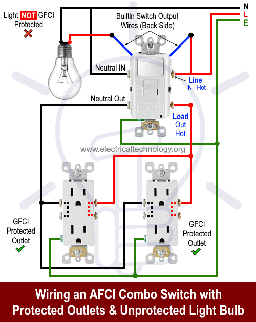
The two ordinary outlets are connected to the load terminal where both are AFCI protected while they can’t be ON/OFF through the switch in the AFCI.
Safety Precautions:
- Switch off the main circuit breaker to make sure the power supply is OFF before wiring a GFCI outlet.
- Use the suitable voltage and ampere rating of switch with appropriate wire size and proper size MCB according to the load rating.
- Use the correct polarity i.e. verify the Load and Line terminals while installing a GFCI for protection. In other words, connect the wires to the correct side of outlet for proper operation.
- Regular maintenance, check and test is recommended while test the portable GFCI before each operation.
- Contact the authorized and licensed electrician for GFCI installation if you are not sure about the wiring diagrams.
- The author will not be liable for any losses, injuries, or damages from the display or use of this information or if you try any circuit in wrong format. So please! Be careful because it’s all about electricity and electricity is too dangerous.
Related Wiring Tutorials:
- Wiring of the Distribution Board with RCD (Residual Current Devices)
- Corridor Wiring Circuit Diagram – Hallway Wiring using 2-Way Switches
- Tunnel Wiring Circuit Diagram for Light Control using Switches
- Hospital Wiring Circuit for Light Control using Switches
- Hotel Wiring Circuit – Bell Indicator Circuit for Hotelling
- Hostel Wiring Circuit Diagram and Working
- Godown Wiring Diagram – Tunnel Wiring Circuit and Working
- Difference Between MCB, MCCB, ELCB & RCD Circuit Breakers
- Even More Electrical Wiring Installation & Tutorials


Excellent
More than Excellent
I can ask some question in French please, because I do not speak english wèl.
Clear and easy wiring diagrams for AFCI Combo Switch.