Maximum Number of Circuit Breakers Allowed in Main Panels and Load Centers
Old 42 Circuit Rule Per Panel
Prior to the 2008 edition of the National Electrical Code (NEC), residential panels were limited to 42 circuits due to concerns about heat generation. This meant that a residential electrical panel could contain no more than 42 overcurrent devices for lighting and appliance branch circuits.
After the 2008 NEC revision, this specific limitation was removed. Today, the maximum number of circuit breakers in a panel is determined by the the manufacturer’s specifications, panel’s physical design, and UL listing, rather than a fixed universal limit.
In some cases, a panel may allow more breakers than the number of standard full-size breaker spaces by using tandem (duplex) breakers where permitted by the manufacturer. However, installing additional breakers beyond the panel’s rated capacity is unsafe and may lead to panel overheating, nuisance tripping, or electrical hazards.
Current Number Of Breaker Allowed Per Panel
In modern installations, the maximum number of circuit breakers is determined by the panel or load center manufacturer as per NEC 110.3(B), not by a fixed code limit.
The panel label, typically printed near the schematic diagram inside the panel, indicates the maximum number of circuit breakers allowed for that specific panel.
Alternatively, the documentation provided with the load center specifies both the maximum number of breaker spaces and the maximum number of circuits permitted.
This is not always the case i.e. this is only applicable if you follow the maximum amps per stab and using non-CTL breakers in a CTL panel.
1 Breaker per Slot
Some panels are specifically designed for one breaker per slot. In this case, a single-pole breaker fits into one slot (i.e., a 120 V breaker connected to a single hot busbar), while a two-pole breaker occupies two adjacent slots (e.g., a 240 V breaker connected to both hot busbars) in the main panel.
1 or 2 Breakers per Slot
Some panels are designed to accept the installation of tandem breakers (also known as duplex breakers) that fit into a single slot and provide two independent circuits.
For example, a “20” panel allows up to 20 standard breakers, or a maximum of 40 circuits using tandem breakers if tandem breakers are permitted in all slots.
Similarly, a “30/45” panel has 30 physical slots and can accept 30 standard breakers, but it can support up to 45 circuits when tandem breakers are installed in designated slots.
Good to Know: According to NEC 408.54, the number of circuits or circuit breakers in a panel must not exceed the panel’s listed capacity.
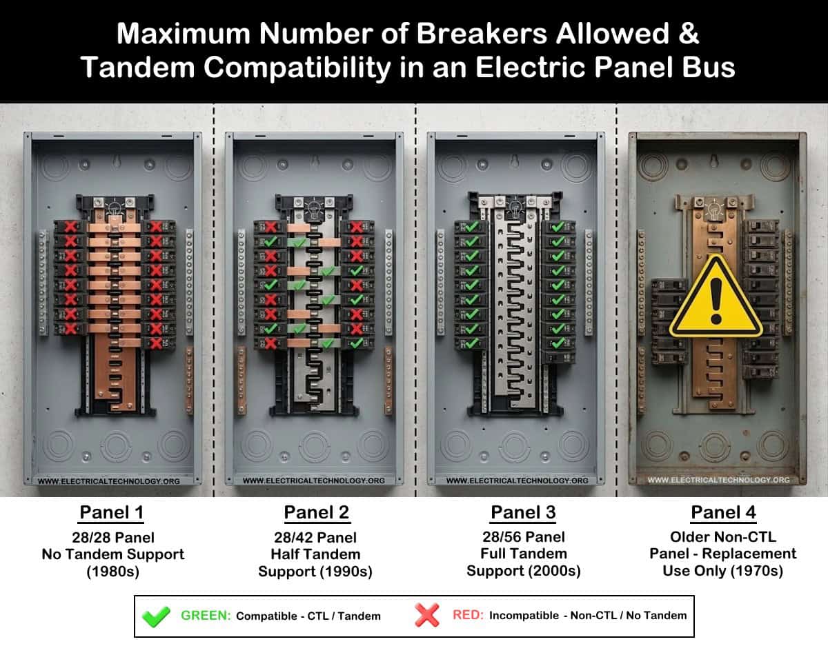
CTL vs Non-CTL Panels & Breakers
As per NEC 408.54, a panelboard must include a physical means that prevents the installation of more overcurrent devices (fuses or circuit breakers) than the number for which the panelboard was designed, rated, and listed.
This requirement is implemented through Circuit Total Limitation (CTL) in panelboards and circuit breakers. In CTL load centers, breakers are mechanically restricted (often by a metal tab or hook) so they can only snap into designated panel slots (CTL slots).
On the other hand, Non-CTL breakers (commonly used in older panels) do not have this limitation. They can physically fit into almost any slot in the panel.
Non-CTL breakers are still manufactured for replacement in older panels. However, some DIY installers misuse them in modern CTL panels because they can physically fit in any slot.
To avoid this issue, always check the circuit breaker nameplate or label printed on it before installation to verify whether the breaker is CTL or Non-CTL and ensure it is compatible with the panelboard.
Warning: Installing a non-CTL breaker in a modern CTL panelboard violates NEC 110.3(B) because the equipment must be used according to its listing and manufacturer instructions. This can lead to a failed inspection and may create a potential fire hazard.
Max Amps per Stab
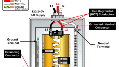
A bus stab (or “bus finger”) in an electric panel is a, metal, conductive tab protruding from the main vertical bus bars that connects to and powers circuit breakers. These stabs allow breakers to snap on securely, often serving two breakers opposite each other (one on each side).
In an electric panel, the number of stabs in a panel is half than the total number of breaker slots. For instance, a panel with 15 stabs has 30 slots.
This limit the number of of breakers in the panel as the manufacture allows maximum amps per stab. The definitive limit is listed on the panelboard’s wiring diagram, often stating “MAX. SUM OF BREAKER RATINGS PER STAB”.
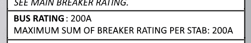
A 200A panel does not mean every single stab can handle 200A simultaneously, the aggregate load is managed by the main breaker.
For opposite breakers, if a 125A breaker is installed in one slot and the stab limit is 200 A, the breaker directly across from it cannot be larger than 75A. This is because the combined rating of both breakers connected to the same branch-circuit stab must not exceed 200A.
In other words, the sum of the ratings of breakers installed on the same stab must be within the manufacturer’s specified limit.
The maximum number of breakers, busbar rating, and the maximum allowable amperage per stab for branch circuits can be found on the panelboard nameplate or data label printed inside the panel. These ratings must always be followed when installing or replacing circuit breakers.
Good to Know: If a 100A main breaker is backfed (connected to a stab), it counts as 100A, not 200A, even if the stabs are rated lower, as it is feeding, not loading, the bus. In short, if a 100A backfeed main breaker is installed on a stab with max amp rating of 150A, the breaker on the other side, (mostly unused – and if used), its rating shall not exceed than 50A.
Precautions:
- Always disconnect the power supply by switching OFF the circuit breaker at the main service panel before performing any electrical work.
- If you are unsure about any part of the installation, consult a licensed electrician and ensure compliance with applicable local electrical codes.
Disclaimer: Electrical work is dangerous. The author assumes no responsibility for any loss, injury, or damage resulting from the use or misuse of this information, including improper circuit installation.
Resources:
Related Posts:
- National Electrical Code (NEC) Requirements for Panelboards
- Busbar, Bus Stab, Breaker Slot and Circuit Space in a Panel
- What is a Backfeed Main Breaker in an Electric Panel?
- What is Double Tapped Breaker and Double Lug in Main Panel
- What Happens if the Neutral is Lost in the Main or Subpanel?
- Why Must Neutral and Ground Wires Be Bonded in the Main Panel?
- Why are Neutral and Ground Wires Separated in a Subpanel?
- Should GFCI Protection Be in the Main Panel or Receptacle?
- Difference Between BR and CH Breakers and Load Centers
- Difference Between Homeline and QO Breakers and Panels
- Difference Between 1-Pole and 2-Pole Breakers – NEC & IEC
- Can the Neutral Wire Cause Electric Shock? Different Cases
- Will I Get an Electric Shock If I Touch the Ground Wire?
- Will a Man Get an Electric Shock If He Hangs on a Live Wire?
- What Happens When You Touch an Electrical Busbar?
- Can We Use AC Circuit Breaker for DC Circuit & Vice Versa?
- Can I Use a 240V Breaker on a 120V Circuit and Vice Versa?
- Can You Use 15A Breaker on 20A Circuit and Vice Versa?
- What is the White Powder on the Circuit Breaker Terminals?
- Why Doesn’t a Standard Breaker Protract Against Ground Faults?
Sizing & Rating
- How to Size a Load Center, Panelboards and Distribution Board?
- How to Determine the Right Size Capacity of a Subpanel?
- How to Size a Circuit Breaker? Breaker Size Calculator
- How to Find the Number of Breakers in a Load Center?
- How to Find the Right Wire Size for 100A Service 120V/240V Panel?
- What is the Correct Wire Size for 100A Breaker and Load?
- How to Find the Number of Lights on a Single Circuit Breaker?
- How to Size a Breaker and Wires in AWG with EGC for Load?
- How to Size a Breaker and Wires in AWG with EGC for Load?
- How to Size a Branch Circuit Conductors with Protection?
- How to Size Feeder Conductors with Overcurrent Protection
- How to Size Service-Entrance Conductors and Feeder Cables?
- How to Size Equipment Grounding Conductor (EGC)?
- How to Size Grounding Electrode Conductor (GEC)?
- How to Size Main Bonding Jumper (MBJ)?
- How to Find the Proper Size of Wire & Cable In Metric & Imperial Systems
Wiring Tutorials
- How to Wire 120V & 240V Main Panel? Breaker Box Installation
- How to Wire a Subpanel? Main Lug Installation for 120V/240V
- How to Wire 120V & 208V – 1 & 3-Phase Main Panel? 3-Φ Load Center Wiring
- How to Wire a GFCI Circuit Breaker? 1, 2, 3 4 Poles GFCIs Wiring
- How to wire a GFCI Outlet? GFCI Wiring Circuit Diagrams
- How to Wire an AFCI Combo Switch – AFCI Switch Wiring Diagrams
- How to Wire a Single-Pole Circuit Breaker in a 120/240V Panel
- How to Wire a Two-Pole Circuit Breaker in a 120/240V Panel
-
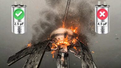 What Happens If You Install a Larger Capacitor in a Fan?
-
 Robotic Snakes that Crawl Power Lines to Detect Faults
-
 Can You Install Breakers and Switches on Neutral Conductor
-
 Difference Between Grounding, Grounded and Ungrounded Conductors
-
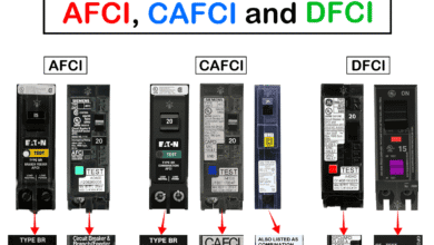 Difference Between AFCI, CAFCI, DFCI and GFCI?
-
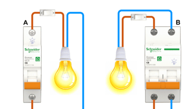 Can You Use a 2-Pole Breaker Instead of a 1-Pole Breaker