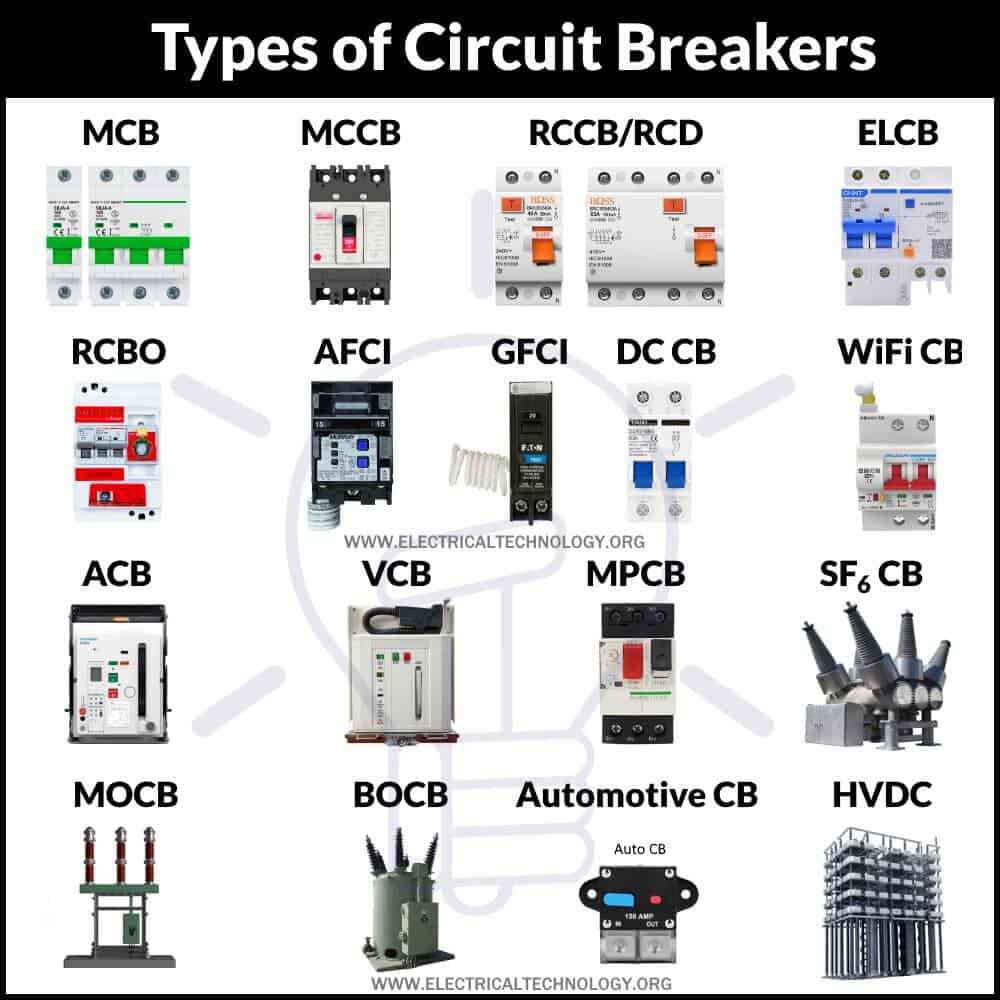
Types of Circuit Breakers – Working and Applications
Different Types of Circuit Breakers – Their Construction, Working and Applications
We cannot imagine our life without electricity especially in this modern era. Almost everything is operated by electricity. Be it a supply from the mains or from a battery, we must keep it in control. Any fault in electricity can cause damage or even become fatal. Therefore, we use multiple protection devices such as circuit breakers to avoid such hazards.
What is a Circuit Breaker?
A circuit breaker is a mechanical switch that automatically operates to protect a circuit from the damage caused by fault current. It automatically breaks the circuit upon sensing a huge draw of current flow due to overloading or short circuit. It can also manually break open the circuit for maintenance or fault clearance. It can safely close and open a circuit to protect it from damage
A circuit breaker breaks the supply to the circuit when the current exceeds its rated current. The current may exceed due to numerous reasons such as overloading, short circuit, voltage spikes, etc. Overloading occurs when the load draws a very huge current more than the rated current. A short circuit occurs when two exposed wires come into contact with each other by any means.
What Must the Circuit Breaker Do?
The main function of a circuit breaker is to safely interrupt the flow of current in a circuit.
- It should momentarily withstand the fault current
- It should safely break open the circuit
- It should quickly extinguish the arc.
- Its terminals should withstand the voltage after breaking.
- It should prevent the arc from re-striking.
The circuit breaker withstands the fault current momentarily and allows other circuit breakers to resolve the fault. The CB is designed to tolerate a specific range of fault current without damaging its terminals.
Once it detects the fault current, it trips and interrupts the current flow. It breaks open the circuit using some sort of stored mechanical energy such as spring or a blast of compressed air to separate the contacts. it can also use the fault current to break open the contacts using thermal expansion or an electromagnetic field using a solenoid.
The next step that comes after the separation of contacts is the arc extinction. The arc is generated between the contacts due to the high voltage between them. It can damage the CB contacts or terminals due to excessive heat generated because of high current.
Mediums Used for Arc Extinction
The electrical arc tries to make the circuit, so the current still flows in it. It must be extinguished and different kinds of circuit breakers use various insulating or dielectric arc extinction mediums such as.
- Air
- Vacuum
- Insulating Oil
- Insulating gas such as SF6 (Sulphur hexafluoride)
Other than the medium being used arch quenching, various arc extinction techniques are used to quickly and safely eliminate an arc.
Methods Used for Arc Extinction
- Cooling of Arc: The arc heats up the air molecule which ionizes and reduces the resistance of the air. Cooling the arc will recombine the ionized particle into its natural state and increase the dielectric strength of the air molecule. As the resistance of the medium increases, the voltage required to maintain the arc also increases and the current starts to drop resulting in arc quenching.
- Air Blasting: Such a method is used in the air blast circuit breaker, where the arc is quenched using a blast of compressed air. The ionized air particles are replaced with non-ionized air molecules that have higher dielectric strength. It increases the resistance thus reducing the current which leads to the extinction of the arc.
- Increasing the length of arc: The arc length is directly proportional to its voltage. Increasing the length of the arc by separating the contact terminals further apart will increase the voltage required to maintain it. Thus it will extinguish.
- Reducing cross-section of arc: Another technique is to reduce the cross-section of arc by reducing the contact sizes. Therefore, the voltage required for arc increases and extinguish it.
- Deflecting the arc: In this technique, a magnetic field is created to deflect the arc. it blows out the arc into a section of the circuit breaker called arc chute where it is cooled off and extinguishes.
- Dividing or splitting the arc: In this technique, the arc is split into multiple arcs by proving multiple contacts in between. The arc is split into numerous small arc in series which increases its length and resistance. Therefore, reducing the arc current and eventually extinguishing it.
- Zero current quenching: this is the most common method used in the AC circuit breaker. There are inherently multiple zero currents in an AC waveform. The circuit is opened at the exact point of zero current. So that the current does not rise to generate arc.
- Using charged capacitor in parallel: This technique is used in DC circuit breaker. The DC does not have natural zero currents. Therefore, a charged capacitor with an inductor is used in parallel to introduce an artificial zero current in the line to extinguish the arc.
Basically, a circuit breaker is necessary to install on every line to protect it from any kind of hazard or disasters. Circuit breakers are manufactured by keeping various features in mind such as;
- Intended Voltage Applications
- Alternating or Direct Current
- Location of the installation
- Design Characteristics
- Method and medium used for current interruption (Arc Extinction)
There are various types of circuit breakers that are differentiated based on various characteristics. Circuit breakers are mainly classified into two types;
- AC Circuit Breaker
- DC Circuit Breaker
Related Post: Can We Use AC Circuit Breaker for DC Circuit and Vice Versa?
AC Circuit Breaker
AC refers to alternating current whose voltage and current fluctuates along the zero value many times in a second. The energy at this zero point is null which can be utilized to break the circuit without generating the arc.
Circuit breakers used for AC are quite different than in DC. The inherent zero crossings in AC provide multiple chances in a second for the arc to extinguish itself.
The strength of the arc is directly proportional to the level of the voltage. Therefore, low voltage arcs can be easily quenched but high voltages arc require a more sophisticated approach to extinguish it. therefore, the CB are classified based on their voltage level.
High Voltage AC Circuit Breaker
The definition of high voltage depends on context. IEC considers high voltages as the voltage that exceeds 1000v. Such voltage has a tendency to generate an arc that is not easily extinguishable. Circuit breakers used for making and breaking contacts at such voltages are called HV circuit breakers.
The arc extinction can be done using various methods in such high voltages. The HV circuit breaker may or may not use OIL for arc extinction; therefore, they are classified into two types:
- Oil Circuit Breaker
- Oil-Less Circuit Breaker
Related Post: Difference Between Relay and Circuit Breaker
Oil Circuit Breaker
The type of circuit breaker that uses oil as a dielectric or insulating medium to quench the arc is called an Oil Circuit Breaker (OCB). It is one of the oldest types of high voltage circuit breaker and it mainly uses the transformer oil. The oil used in such circuit breakers has very good insulating properties far better than air. The CB contacts are submerged in oil which is used to quench the arc once the contacts separate. The heat generated by the arc is dissipated inside the oil.
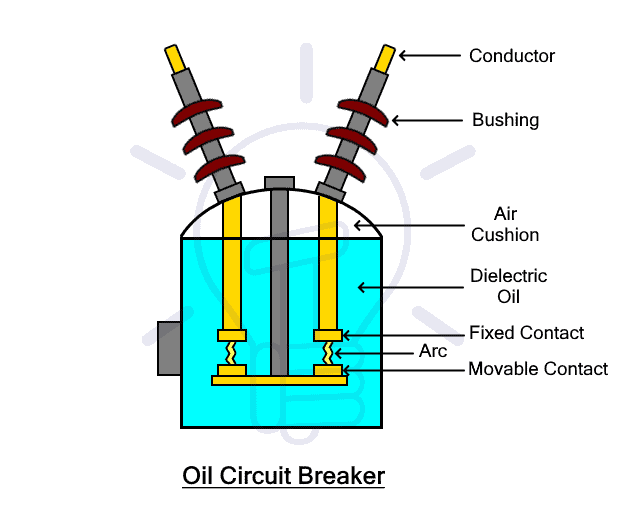
When CB breaks its current-carrying contacts inside the oil, the distance between the contacts starts increasing. Initially, there is a very small distance between the contacts but there is also a very high voltage gradient. Due to this, the oil between the contacts starts ionizing and creates an arc between the contacts.
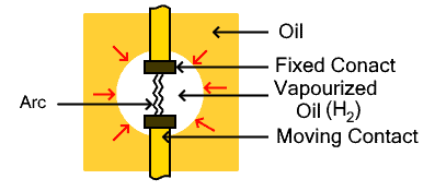
The arc generates a lot of heat and vaporizes the oil surrounding it which is mostly decomposed into hydrogen gas. The hydrogen gas bubbles are rapidly generated surrounding the contact almost ten times the volumes of the oil. This oil surrounding the gas bubbles put a lot of pressure on it increasing de-ionization of the medium. De-ionization of the medium increases its dielectric strength that will quench the arc at zero crossing of the current.
Besides that, the cooling effect of the oil and the gas bubbles also helps in arc quenching.
Based on the amount of oil being used in OCB (Oil Circuit Breaker), they are classified into two types
- Bulk Oil Circuit Breaker (BOCB)
- Minimum Oil Circuit Breaker (MOCB)
Related Posts:
- Types of HVDC Systems and MTDC Configurations
- Types of FACTS (Flexible AC Transmission System) Controllers and Devices
Bulk Oil Circuit Breaker (BOCB)
Such type of oil circuit breaker uses the insulating oil to quench the arc as well as insulate the live contacts from the earthed parts of the CB. Such CB uses oil in bulk.
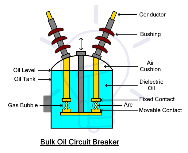
BOCB has an iron tank that holds the insulating oil inside. The contacts (fixed and moving) are submerged inside the oil. Upon breaking the contacts, the arc generates heat and produces gas. The pressurized gas displaces the oil inside the tank where air at the top of the tank is used as a cushion. Therefore, the tank should not be completely filled with oil. Also, the tank must be strong enough to absorb the pressure released by the gas. There is also a gas vent for releasing the gas safely outside.
The arc is quenched by utilizing the compressed gas generated by the heat of the arc. Since the contacts are moving, the distance is also increased between the contacts. it also increases the resistance for the arc. Also, the cooling effect of the gas also plays its role in quenching the arc once the current goes through zero crossing.
The BOCB is divided into further two types based on the division of arcs to quickly extinguish it.
Single Break Bulk Oil Circuit Breaker
In single break BOCB, there is only one fixed contact and one moving contact. Upon fault current, the moving contact pushes backward generating an arc that is extinguished by the compressed gas inside the oil. As the name suggests, there is only one break between the contacts.
Double Break Bulk Oil Circuit Breaker
In double break BOCB, there are two fixed contacts and one moving contact. The fixed contacts are fixated to the tank at both ends connected to the live conductors while the moving contact can move upward and downward using an insulating rod.
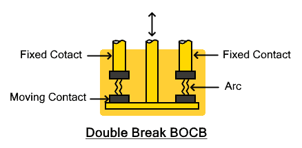
In normal conditions, the moving contact is pushed upward to make the contact at both ends with the fixed contacts. upon fault conditions, the moving contacts is pulled downward to break the contacts and generating arcs at both ends. This way, the arc is split into two parts having lower strength which can be easily cooled off and quenched inside the oil.
Advantages
- The oil used for arc quenching has very high dielectric strength
- The oil insulates the live contacts from the earthed parts
- The oil produces hydrogen gas with the heat from the arc which is beneficial for arc quenching.
- The pressure of oil compresses the gas to deionize the medium.
- The gas also helps in cooling the medium.
Disadvantages
- The oil is inflammable and causes a fire hazard.
- The contacts can get damaged with the arc.
- The carbonization of the oil from the contacts reduces its dielectric strength.
- The contacts and the oil must be checked and maintained regularly.
- The use of huge amount of oil increases its cost
- Their large oil-filled tanks are heavy and take large space.
Minimum Oil Circuit Breaker (MOCB)
As we know the bulk oil circuit breaker uses a huge amount of oil to quench the arc which may pose a threat for fire hazard. To reduce such risk, the MOCB uses far less oil than in BOCB. The oil is only used for arc quenching and not to isolate the live parts from earthed parts.
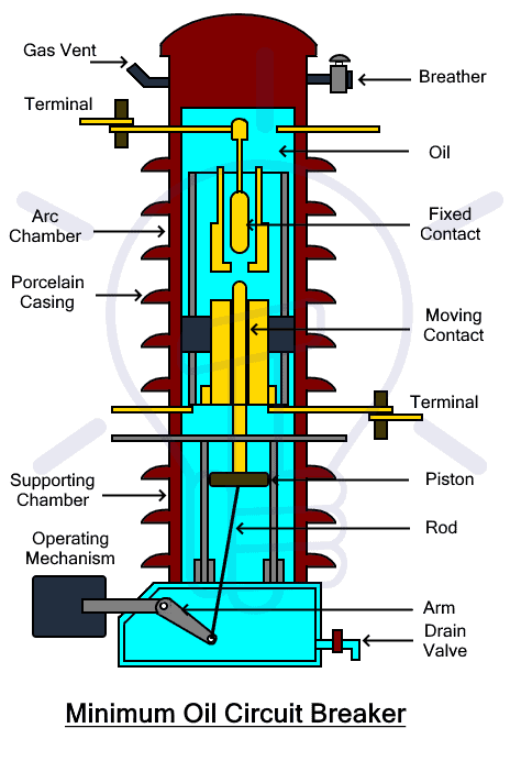
MOCB has two chambers: the arc chamber and the supporting chamber. The arc chamber is made from porcelain encased with bakelised paper. It is filled with insulating oil. This chamber is used for quenching the arc. It contains fixed and moving contacts.
The supporting chamber is made from porcelain mounted on top of a metal chamber. This chamber is used for isolating the arc chamber as well as support the arc chamber by mounting it on top of it. this chamber is also filled with oil used only for insulation.
The moving contact moves upwards and downwards with the help of a fixed armed in the supporting chamber. The moving contact has a fixed piston which is used for forcing the oil upwards helping to quench the arc.
Under normal conditions, the lower moving contact makes a connection with the upper fixed contact. Upon fault condition, the arm pulls the moving contact downward and an arc is generated. This arc is extinguished by the pressurized gas in the oil surrounding it and by pushing the oil from the support chamber with the help of the piston. As the contact moves downward, a vent becomes available for the hydrogen gas to exhaust out.
In terms of venting, MOCB is divided into two types.
Axial Venting MOCB: In axial venting MOCB, the arc chamber vents are designed in such a way when the moving contacts slide downward to break the circuit. it allows an opening for the cool oil to move in from the lower vent which sweeps the arc in axial direction through the upper vent.
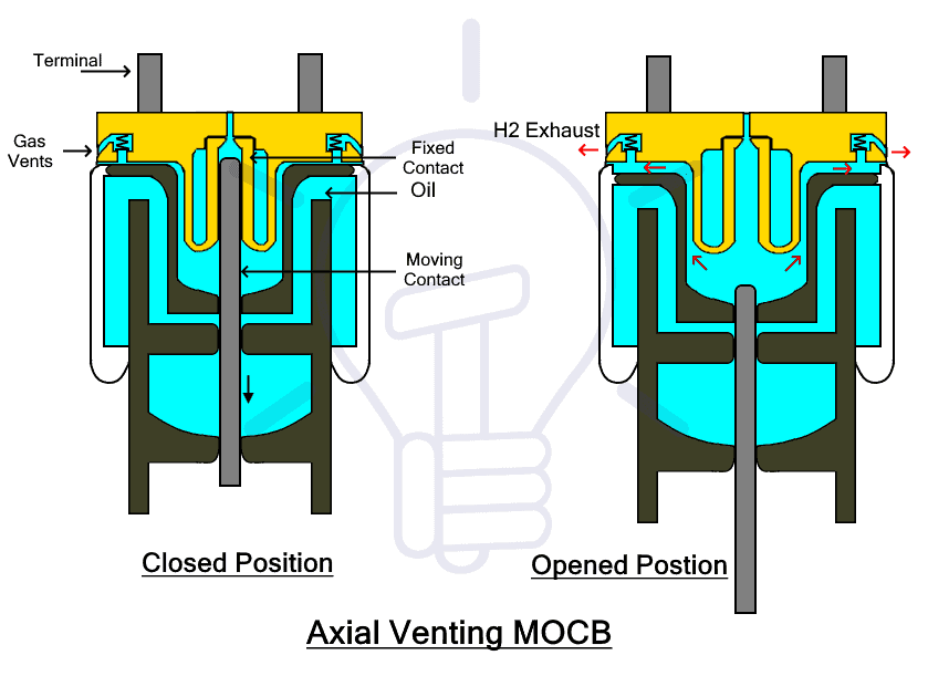
The axial venting generates very high pressure thus having very high de-ionization capabilities and consequently high dielectric strength of the oil. It is used for low current at high voltages.
Radial Venting MOCB: While in radial venting MOCB, the vents are designed radially along the arc chamber. Therefore, the arc is swept radially through the multiple vents.
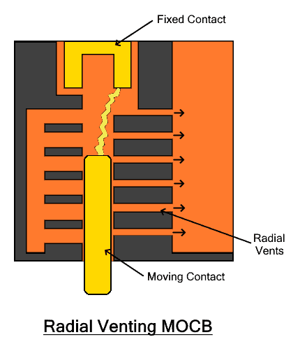
The radial venting has low pressure thus the oil has low dielectric strength. Therefore, radial venting MOCB is used for high current at low voltages.
A combination of both axial and radial venting is used inside a single MOCB to break both low and high voltages efficiently.
Advantages
- It requires a very less amount of oil.
- Less amount of oil means the risk of fire hazard is low.
- It has low weight.
- It has small size and takes up small space
- It is cheaper than BOCB.
- It has easier maintenance and oil can be easily replaced.
- Best for installation in places where it is not frequently used.
Disadvantages
- Lesser oil is more affected by the amount of carbonization from the contacts.
- The oil quickly losses its dielectric strength.
- It requires more frequent maintenance.
Related Post: How to Read MCB Nameplate Data Rating Printed on it?
Oil Impulse Circuit Breaker
In the MOCBs discussed above, the pressure is developed by the arc which is dependent on the amount of the arc current. Therefore, they are not suitable for low current arc quenching. Oil impulse CB is another type of MOCB where the necessary pressure is developed by external mechanical means using a piston connected with the moving contact. The pressure developed in such a way is independent of the fault current. it uses far less oil than conventional MOCB and it can extinguish the arc independent of its current and voltage.
Oil less Circuit Breaker
Such type of high voltage circuit breaker does not use oil as arc quenching medium. There are different types of arc quenching mediums that can be used instead of oil. Following are the type oil-less CBs using various arc quenching medium;
- Air Circuit Breaker
- Air Blast Circuit Breaker
- SF6 Circuit Breaker
- Carbon Dioxide Circuit Breaker
- Vacuum Circuit Breaker
Air Circuit Breaker (ACB)
Air Circuit Breaker or ACB is a type of HV oil-less circuit breaker that uses air as its arc extinguishing medium. It is used for short circuit and overcurrent protection up to 15KV and 800 to 10K Amps. It is preferable than oil circuit breaker due to the absence of inflammable oil and the risk of fire hazards.
As we know, the objective of a circuit breaker is to safely extinguish the arc and prevention of arc re-striking. In order to extinguish the arc, we have to increase the arc voltage (minimum voltage required to maintain the arc). ACB uses the air as a medium to extinguish the arc. Unlike the other mediums, the air can be used in various ways to extinguish the arc by using various methods such as cooling the arc, increasing the arc length, splitting the arc and air blasting, etc.
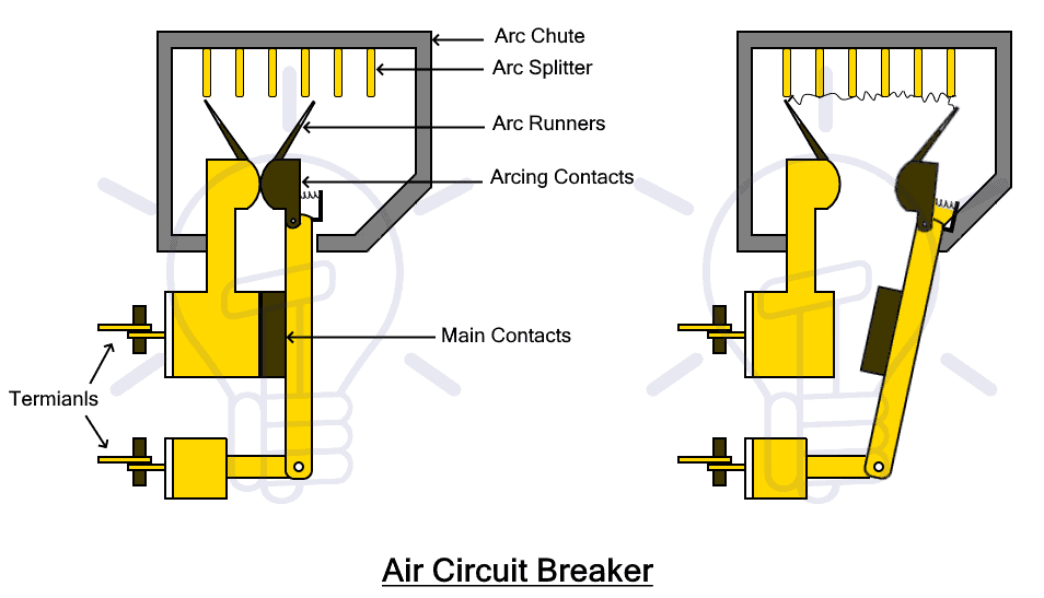
In ACB, there are two pairs of contacts i.e. main contacts (made of copper) and arcing contacts (made of carbon). Under normal conditions, the main contacts are used for the normal supply of current. Under fault current, the main contacts open while the arcing contacts remain closed.
As soon as the main contacts open up, the current will flow through the arcing contacts. at this point, there is no arc and the main contacts are safe. The arc generates once the arcing contact opens up. The arc sweeps upwards resulting in cooling and increasing the length of the arc. Thus the arc is extinguished at zero current.
ACB is further divided into the following types.
- Plain Air Circuit Breaker
- Arc-Chute Circuit Breaker
- Magnetic Blow Out Circuit Breaker
- Air Blast Circuit Breaker
Related Post: Air Circuit Breaker (ACB) – Construction, Operation, Types and Uses
Plain Air Circuit Breaker
A plain air circuit breaker is the simplest air circuit breaker. It is also known as cross blast circuit breaker. It has a chamber surrounding the main contacts. This chamber is called arc chute. It is used for extinguishing the arc made from refractory material. It has multiple small compartments made from separation of metallic plates.
The metallic separation inside the arc chute acts as an arc separator and it divides the arc into small arcs that increase the voltage required to maintain the arc. The air also sweeps the arc upwards causing it to cool off. Thus arc is extinguished at zero current. It is used for low voltage applications.
Air Chute Air Break Circuit Breaker
The air chute air break circuit breaker has two types of contacts i.e. main contacts and arcing contacts. The main contacts are made from silver-plated copper to reduce its resistance. The arcing contacts are made from a copper alloy that has very high heat resistance to absorb the damage from arcing.
Under normal operation, both contacts are closed. The main contacts conduct current due to their low resistance. When the main contacts open, the current diverts through the arcing contacts. Afterward, the arcing contacts are open where the arc is established and extinguished. The arcing contacts are easily replaceable in case of wear and tear.
Magnetic Blowout Air Circuit Breaker
Such type of Air circuit breaker has a blowout coil that generates a magnetic field. This magnetic field deflects the arc into the arc chute to extend its length as well as cool it. The arc is extinguished inside the breaker. The magnetic field does not directly extinguish the arc but merely deflects it which is later extinguished by the air. It offers control over the arc to increase its voltage. These circuit breakers are used for up to 11KV.
Air Blast Circuit Breaker
Air Blast Circuit Breaker or ABCB uses a blast of compressed air for the arc interruption. The air is stored and compressed in a tank. This air is released through a nozzle at a very high speed to extinguish the arc. They have high voltage capacity of up to 450KV. They are used for 220KV lines in switchyards.
The air blast circuit breaker is further divided into four types
- Axial Blast Air Circuit Breaker
- Axial Blast with sliding moving contact ACB
- Radial Blast Air Circuit Breaker
- Cross Blast Air Circuit Breaker
Axial Blast ACB
In axial blast ACB, the air blast flows axially in the same direction as the arc. The air blast lengthens and cools the arc at the same time and also increases the dielectric strength of the medium to prevent the arc from re-striking.
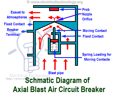
The moving contact under the force of spring is in closed position with the fixed contact. The fixed contact has a nozzle orifice blocked by the tip of the moving contact. The compressed air is stored in the tank below it. Upon fault condition, the compressed air is released that pushes the spring to pull the moving contact, thus opening the nozzle orifice in the fixed contact. The arc strikes between the contacts that is lengthened and cooled by the blast of air flowing through the orifice. It all happens simultaneously and the arc is extinguished.
- Related Post: Difference between Fuse and MCB
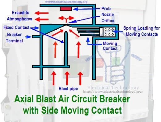
Axial Blast ACB with Sliding Moving Contact
This type of breaker is a modified form of the axial blast ACB. It has a moving contact horizontally fitted on a spring with a piston. The fixed contact has the same kind of nozzle orifice which is blocked by this moving contact. it has the same arc quenching operation as discussed in the previous ACB.
Radial Blast ACB
In radial blast ACB, the contacts are hollow like a tube i.e. there is free space inside the moving contact as well as fixed contact. The free space is used for the flow of compressed air to cool the arc. The air blast flows radially inside the contacts along the arc therefore it is called radial blast ACB.
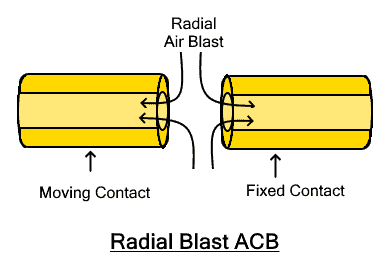
Under fault conditions, the arc is formed between the contacts when they are separated. The radial blast of air cools off the arc and increases the dielectric strength between the contacts. Upon zero current, the arc is extinguished.
Cross Blast ACB
In cross blast ACB, the air blast is directed at a right angle to the arc. The air blast is used to deflect and lengthen the arc into the arc chamber where arc splitters split and lengthen the arc to extinguish it. There is exhaust in the arc chamber for the air to flow out.
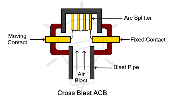
The air tank is fixed in the perpendicular direction to the movement of the contacts. Upon fault condition, the contacts are opened and arc is established. At the same time, the air blast is released that sweeps the arc into the arc chamber. The arc splitters split the arc that is eventually quenched at the zero current. The air blast also increases the dielectric strength of the medium between the contacts to prevent the arc from restriking.
Advantages of ACB
- ACB does not have any fire hazards, unlike oil circuit breakers.
- ACB has a very high speed i.e. its arc quenching is very fast.
- The speed of arc quenching is the same for all values of current.
- It has small size due to small space required for an air blast to cool and quench the arc.
- It is used for frequency operation where circuit breaking and making is done often such as in switchyards.
- It is very reliable and consistent because short arcing time cannot wear the contact quickly.
- It requires less maintenance due to less wearing of the contacts.
- ACB is fairly cheaper as air is used as the arc quenching medium.
Disadvantages of ACB
- The air compressor needs to be maintained to have the correct pressure at all the time.
- The air compressor takes up a large space.
- The air pipes junction may leak air pressure.
- There is a chance of a high rate rise of re-striking voltage and current chopping.
- The air release produces a noise.
- Air as compared to other insulating gases has lower extinguishing properties.
Related Post: Difference Between Circuit Breaker and GFCI
Sulphur Hexafluoride (SF6) Circuit Breaker
Sulphur Hexafluoride or shortly known as SF6 is a non-flammable and insulating gas that has very high electronegativity. It has a high tendency to absorb electrons.
When the arc is struck between the contacts, the medium is ionized due to free electrons. The SF6 absorbs the free electrons and form negative ions that are far heavier than free electrons. Due to their heavyweight, they are immobile and reduces the mobility of charges. This enhances the dielectric strength of the medium where the arc is quenched. The SF6 has far more superior insulating and arc quenching capabilities than air almost 100 times better.
The SF6 is very expensive and a greenhouse gas. SF6 itself is not toxic but its product gases are toxic and Its emission is dangerous for the environment. Therefore, a close circuit gas system is designed for such breaker where the SF6 gas is reutilized after each operation. The system also monitors its pressure which is directly proportional to its dielectric strength.
There are three types of SF6 Circuit Breakers
- Non-Puffer Type SF6 Circuit Breaker
- Single Pressure Puffer Type SF6 Circuit Breaker
- Double Pressure Type SF6 Circuit Breaker
Non-Puffer Type
In non-Puffer SF6 CB, pressurized SF6 gas is stored in the gas chamber. While the arc quenching is done inside an interrupter unit. This unit has moving and fixed contacts that are basically hollow cylinders. The fixed contact has arc horns while the moving contact has vents for pressurized gas to flow.
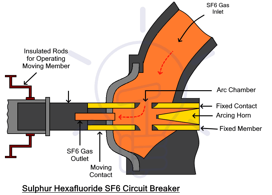
Under a fault condition, the moving contact is moved apart from the fixed contact. Its movement is synchronized with the valve of the gas chamber. as soon as the contacts open, the valve is opened and pressurized SF6 is introduced into the arc chamber. The SF6 quench the arc and flows through the hollow moving contact. This gas is then recombined and pumped back into the gas chamber for re-utilization.
Non-Puffer SF6 circuit breakers were used when they were first invented. Nowadays easier and simple SF6 breakers are used that utilize the puffer cylinder.
Single Pressure Puffer Type SF6 Circuit Breaker
Such type of SF6 CB has a Puffer cylinder. A puffer cylinder is a hollow cylinder that acts as a bridge between two fixed contacts. The cylinder can slide upward and downward axially along the contacts. There is a stationary piston inside the puffer cylinder as shown in the figure. By moving the cylinder, its internal volume can be varied.
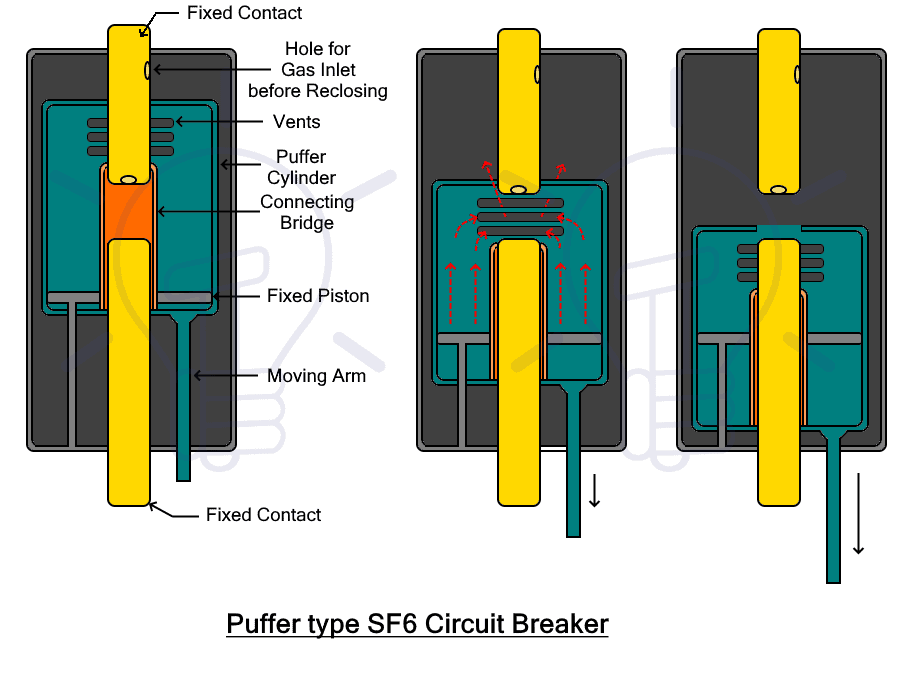
The movable cylinder is filled with SF6 gas. During circuit breaking operation, the cylinder moves downward against the piston to break the connection between the fixed contacts. Consequently, it reduces the volume inside the cylinder, compressing the SF6 inside it.
At this point, the upper fixed contact blocks the vents in the puffer cylinder, therefore the SF6 cannot flow out. By moving the cylinder further down, the vents are unblocked and the contacts are opened. An arc is generated as well as the SF6 starts flowing out through the hollow contacts. This pressurized SF6 quenches the arc.
The same process is done in reverse to close the circuit. by moving the cylinder upwards, its volume is increased as well as a low pressure is generated. Due to this, the SF6 from the surrounding flows into the cylinder through the contacts and the vents.
Double Pressure Type SF6 Circuit Breaker
Such types of SF6 Circuit breakers are obsolete. In such breakers, the gas is compressed and stored in a chamber which is released upon opening of the contacts to quench the arc. It has the same operation as air blast CB except the gas is recompressed and stored in the gas chamber.
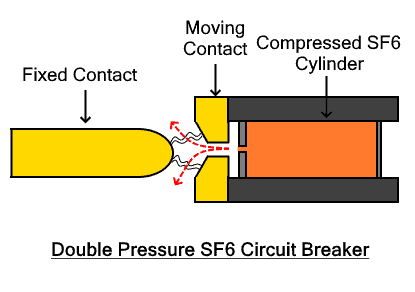
There is SF6 cylinder inside the moving contact that is blocked by fixed contact in closed position. When the contacts separate, an arc is produced. At the same time, the highly pressurized gas from the cylinder rushes out to the low-pressure area. The blast of SF6 quenches the arc as discussed earlier. The gas is filtered, compressed and restored in the cylinder for reuse. It is obsolete due to the complicated gas system required to maintain the gas. It also includes a heater in case the gas is liquefied due to low temperature.
Advantages of SF6 Circuit Breaker
- Sulphur Hexafluoride SF6 has superior arc quenching property almost 100 times more effective than air.
- The arcing time of the SF6 circuit breaker is very short.
- The dielectric strength of SF6 gas is 2 to 3 times higher than air. It also increases with increasing pressure.
- Due to high dielectric strength, the required contact separation is small to prevent arc restriking.
- High dielectric strength leads to large current interruption capabilities.
- The SF6 CB has a compact design. Thus require small space and cost for installation.
- SF6 gas can handle all kinds of switching phenomena.
- SF6 CB has a closed circuit gas system with no leakage. Therefore, best for any installation in any kind of (extreme) environment.
- No carbon particles are formed with arcing, thus the dielectric strength does not reduce.
- It does not require an expensive and bulky air compressing system except for double pressure type which is obsolete.
- The operation of SF6 CB is noiseless.
- SF6 gas is non-toxic in its pure state.
- SF6 gas is non-flammable, thus no chance of fire hazards.
- Since its operation is flawless, it requires less maintenance.
Disadvantages of SF6 Circuit Breaker
- The byproducts formed from SF6 gas during arcing are toxic for the environment but they are mostly recombined into SF6
- The decomposed SF6 is toxic.
- SF6 is an expensive gas so these circuit breakers are costly.
- Leakage of SF6 from the joints must be continuously monitored.
- It requires special transportation and maintaining of the quality of gas.
- The SF6 is heavier than oxygen and can cause difficulty in breathing.
- Recombination and reconditioning of the SF6 gas requires additional equipment.
Related Post: How to Wire an AFCI Breaker? Arc Fault Circuit Interrupter Wiring
Vacuum Circuit Breaker (VCB)
A Vacuum Circuit Breaker or VCB is a type of circuit breaker that uses the vacuum as the arc quenching medium. The vacuum has very high dielectric strength and arc quenching properties far more superior than any other medium. It can quickly recover its dielectric strength. Due to its high dielectric strength, VCB requires a very small gap between its contacts to prevent restriking. The pressure of the vacuum used in VCB is in the range of 10^-7 to 10^-5 torr (1 torr = 1mm of Hg). It is suitable for switching medium-voltage ranging from 22kV to 66 kV.
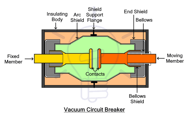
The switching operation of current-carrying contacts and the arc interruption occurs inside a closed chamber called Vacuum interrupter. Its outer insulating body is made up of glass or ceramic material. It consists of fixed and movable contacts surrounded by arc shield.
The arc shield is used for the prevention of the deterioration of the dielectric strength of the vacuum by preventing the ionized metallic vapors on the inner side of the outer insulating body. The movable member is connected to a controlled mechanism (for movement) using bellow. The bellow completely seals the vacuum chamber and prevents any leak.
The operation of VCB is very simple, the arc interruption occurs inside the vacuum upon first zero current. When a fault condition occurs, the contacts are separated. During separation, the contacts do not separate at once but its contact area is reduced which eventually reduces to a single point.
The amount of current passing through this single point heats up the contact and vaporizes (reducing the dielectric strength of the vacuum) to create a medium for the arc. Thus the arc is generated. At next zero current, the conducting metallic vapors re-condenses on the contact surface and the dielectric strength of the vacuum is recovered.
Since the contacts are separated and there are no vapors between them, the arc cannot re-strike. In simple words, a VCB quenches the arc by producing the high dielectric strength to prevent arc re-striking after the current zero.
Since the arc is generated due to the ionization of the contacts, its material plays a vital role in keeping the CB reliable and maintenance-free. Therefore, the VCB contact material must have the following properties
- It must have high electrical conductivity to avoid overheating upon normal load currents.
- It must have high thermal conductivity to dissipate large heat produced during arcing.
- It should have high arc withstanding capabilities and low current chopping level.
- It must have low resistance with high density.
The contacts are made from copper alloy such as Copper-bismuth, copper-lead, and copper-chromium material.
Advantages of VCB
- Vacuum is the absence of matter thus VCB has no fire hazards
- The Vacuum has very high dielectric strength and superior arc quenching properties than air and SF6.
- Due to high dielectric strength, VCB requires a small contact gap to extinguish the arc.
- VCB is compact and requires small installation space.
- It is free of maintenance thus it’s reliable having a long life.
- It does not produce any noise doing the operation.
- There are no toxic exhaust gases.
- Its operation is very fast.
- It is suitable for repeated use.
- It can break all types of fault currents.
- Since there is a vacuum, the control mechanism requires less power to move the contacts.
Disadvantages of VCB
- A single vacuum interrupter can only interrupt up to 38kV.
- For interrupting voltages more than 38kV, multiple vacuum interrupters must be connected in series.
- It’s uneconomical for voltages exceeding 38Kv since it requires more than one VCB and the total cost increases.
- In case of loss of vacuum, the VCB becomes useless.
Low Voltage AC Circuit Breaker
The circuit breakers that are used for breaking and making circuits below 1000 volts are called low voltage circuit breakers. The definition of low voltages depends on its context being used for. According to IEC, low voltage refers to voltage below 1000v. Arc generated at such voltages are easily extinguishable. LV circuit breakers are mostly used for residential and industrial applications.
Following are some of the low voltage AC circuit breaker:
- Miniature Circuit Breaker (MCB)
- Molded Case Circuit Breaker (MCCB)
- RESIDUAL CURRENT CIRCUIT BREAKER (RCCB)
- GFI or GFCI circuit breaker (Ground fault circuit interrupter)
- Arc Fault circuit interrupter (AFCI)
- Common trip (ganged) breakers
- Magnetic circuit breakers
- Thermal magnetic circuit breakers
Miniature Circuit Breaker (MCB)
MCB or Miniature Circuit Breaker is an automatically operated electromechanical device used for the protection of the circuit from overloading or short circuit. It breaks or opens the circuit when the current flowing through it exceeds its rated limit. MCB is used for the protection of low voltage circuit 240/415 v AC having a wide range of current ratings below 125V.
MCB doesn’t trip (switch off) instantly, instead there is a time delay between fault occurrence and the breaking of contacts. Generally, they are designed to have a time delay of less than 2.5 millisecond for short circuit and 2 sec to 2 min for overloading. It is to make sure the CB does not trip every time with a momentary surge or starting of inductive load due to high inrush current from such loads such as electrical motors.
MCB does not have adjustable trip characteristics. While the breaking mechanism could be either thermal or thermal-magnetic in operation. The thermal breaking mechanism is used in case of overloading while the magnetic breaking mechanism is used in case of short circuit.
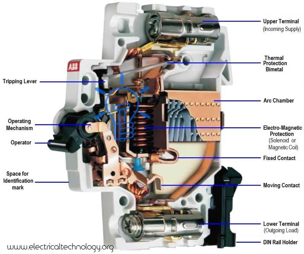
MCB is enclosed in an insulating casing. The fixed and moving contacts made of copper or silver alloy connects with the two terminal for current supply. There is an arc chute consisting of multiple conducting plates called arc splitters that dissipate the arc energy. While the operating mechanism as discussed earlier is of two types i.e. thermal and magnetic.
The thermal tripping mechanism consists of a bimetallic strip (made from two different metals having different thermal expansion) usually made from steel and brass is used for breaking the circuit in case of overloading. When the current above-rated limit starts flowing through the metallic strip, it heats up and starts expanding due to which it bents and triggers the latch to separate the contacts.
The magnetic tripping mechanism consists of a coil or solenoid that produces a magnetic field when current flows through it. In case of a short circuit or very high current, the solenoid produces a strong magnetic field to pull the lever and separate the contacts.
Molded Case Circuit Breaker (MCCB)
MCCB or Molded Case Circuit breaker is an electromechanical circuit breaker having very high current ratings up to 2500 Amps. It is used in applications where the current ratings exceed the range of MCB (Miniature Circuit Breaker). It offers a thermal-magnetic tripping mechanism where the thermal mechanism is used for overloading and magnetic is used for short circuit conditions. It can interrupt current around 10k – 200k amps.
The best and most prominent part of MCCB is that its trip characteristics are adjustable in any current rating. MCB does not have such a feature. MCCB is suitable for applications where normal current is above 100 amps. They are installed in industries.
MCCB can have fixed or interchangeable trip unit. The trip unit is responsible for breaking the contacts upon meeting the fault condition. It provides three types of functions:
Overloading: Overloading occurs when the current exceeds a certain limit for a specific duration. Such current can damage the equipment and wiring and cause fire hazards. MCCB uses a bimetallic strip to protect against overloading.
The bimetallic strip is made of two types of metal having a different rate of heat expansion. The current flowing is used for heating the strip by either using a heater coil or directly conducting it through it. The strip heats up and bents thus tripping the mechanism.
Short Circuit: Short circuit current refers to the fault current in the system due to a downed line or broken exposed wires that come in contact or faulty equipment. the current flow due to short circuit is very large far more than the overloading current.
Short circuit must be interrupted in the shortest period of time possible. MCCB can trip SC currents up to 10K-200K amps in the duration of 0.04 seconds.
Manual Switching
MCCB can also act as a manual switch to switch ON/OFF the power supply to the circuit. It can manually break the power supply in case of emergency or maintenance.
Related Posts:
Advantages of MCCB
- MCCB has an adjustable trip setting.
- It can interrupt very large currents.
- It has a movable trip unit.
- It has a very small tripping time thus fast switching during fault current.
- It also offers remote ON/OFF feature.
- It has a compact design and takes less space.
Earth Leakage Circuit Breaker (ELCB)
ELCB stands for earth leakage circuit breaker. It is a type of circuit breaker that breaks its circuit upon sensing of leakage current. Leakage current occurs due to insulation failure of the wiring and it can flow through a person’s body and cause electrical shock. Thus they are used for protection against electrical shock. They do not offer protection against overloading or short circuit. Therefore, they must be used in series with an MCB.
There are two types of ELCB;
- Voltage ELCB
- Current ELCB (aka RCCB)
Both types of ELCB detect the leakage current but their sensitivity and the level of protection they offer are different. Voltage ELCB was invented before current ELCB. Voltage ELCB is inferior to current ELCB. Therefore, to avoid confusion, the voltage ELCB is renamed ELCB while the current ELCB is renamed as RCCB.
Voltage ELCB
Voltage ELCB operates on voltage level between earth and the body of the equipment. Such ELCB has an extra terminal for earth connection which is directly connected to the load or equipment’s body. If the load’s body comes in contact with the live wire, it may cause electrical shock upon touching it.
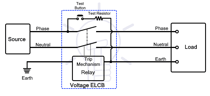
A relay is connected in series with the earthed wire. This relay senses voltage difference between the body and earth. It trips the circuit breaker off if there is a substantial amount of current flow through the earth wire due to the potential difference.
However, ELCB cannot sense the current leakage if a person comes in contact with a live wire. Therefore, ELCB cannot offer protection for other types of leakage current. Furthermore, it also requires an earth connection which is not required in RCCB discussed next.
Related Posts:
Current ELCB (RCCB or RCD)
Current ELCB is generally known as RCD or RCCB. Residual Current Device (RCD) or Residual Current Circuit Breaker (RCCB) is a type of ELCB that breaks the circuit in case of leakage current. It helps in protection against electrical shock or downed line.
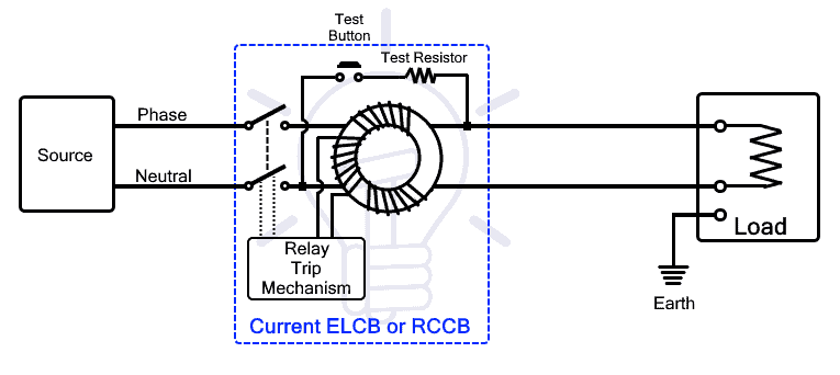
The current leakage occurs when the current flows in an unintended path. In normal conditions, the current flows into the load through a hot or live wire and flows out of the load through the neutral wire. The current leaks if the current flows out through the ground wire or through a person’s body connected with the ground.
RCCB works on the principle of Kirchhoff’s current law, according to which the amount of current entering the circuit must be equal to the amount of current leaving the circuit. It continuously monitors the current in the hot wire and neutral wire.
The difference between these two currents is called residual current. When there is an imbalance in the circuit, the residual current will trip the circuit breaker.
The live and neutral wire goes through a zero-sequence current transformer (it is used for sensing an imbalance of current between the two wires). The live and neutral wire is used for current going into and out of the circuit respectively. Since the amount of current is same in both wires, their flux cancels each other.
when the imbalance occurs due to any ground fault, the resultant flux induces a voltage in the current transformer which is connected with a relay that breaks the circuit.
Type AC RCCB
Such type of RCCB is sensitive to only alternating current and cannot offer protection against DC or any other waveform.
Type A RCCB
Such type of RCCB is sensitive to AC as well as pulsating DC or square waveform
Type B RCCB
Such type of RCCB offers protection against AC up to 1000Hz, Pulsating DC as well as smooth DC.
Limitations of RCCB
- It does not offer protection against overloading and short circuit.
- It does not protect against line-to-neutral electrical shock.
- It is sensitive to only specific waveforms and does not guarantee to protect from other waveforms.
Related Post: Electronic Circuit Breaker – Schematic and Working
Residual Current Breaker with Overcurrent (RCBO)
RCBO or Residual Current Breaker with overcurrent is a circuit breaker that is made from the combination of RCCB and MCB. It offers both the functions of the RCCB and MCB i.e. the protection against residual current or ground fault current and overcurrent.
Residual Current: It is the imbalance in the current between live and neutral wire due to the leakage of current to the ground. RCBO offers protection against it to prevent electrical shock.
Overcurrent: Overcurrent means when the current exceeds its limit. It occurs due to two reasons: Overloading and short circuit.
Overloading: It occurs due to huge current draw above rated current for a prolonged duration that can damage the wiring as well as the components.
Short circuit: it occurs when the live and neutral wire comes into direct contact with each other. There is a huge amount of current flow that can damage electrical equipment.
The RCBO offers protection against both types of fault that is offered individually by RCCB and MCB.
Related Posts:
Ground Fault Circuit Interrupter (GFCI)
A Ground Fault Circuit Interrupter (GFCI) is a type of circuit breaker that protects against electric shock by quickly shutting off power when it detects an imbalance in the electrical current. This imbalance typically occurs when current is leaking somewhere, such as through water or a person. GFCIs are commonly used in areas where water and electricity are close together, like bathrooms, kitchens, and outdoor outlets.
GFI (Ground Fault Interrupter) is a similar term that is sometimes used interchangeably with GFCI. However, technically, GFI is a type of outlet that provides similar protection as a GFCI but does not offer the same level of overall circuit protection as a GFCI circuit breaker does for an entire circuit.
Arc Fault Circuit Interrupter (AFCI) Circuit Breaker
AFCI stands for Arc Fault Circuit interrupter; it is another type of low voltage circuit breaker that offers protection against Arc faults. An arc fault is a high power discharge between two broken conductors. These arcs can generate enough heat to start fire and cause serious damage to property and life. The AFCI breaks the circuit upon sensing any arc in the connected circuit.
The arcs are generated due to incorrect or loose joints in cables or damaged cables by nails, twisting, kinking, etc. Any loose connection in a PowerPoint or old cables may also cause an electrical arc. It can start fire and disrupt and damage any sensitive electronic equipment.
The arcs generate a non-periodic waveform that is detected by using a sensitive logic circuit. It discriminates between a normal arc (occur during switching) and an arc fault. As soon as the arc is detected the circuitry trips the power supply but it cannot prevent the first arc. Although it can prevent the ones that follow and avoid a potential fire hazard.
Common Trip (Ganged) Circuit Breakers
A common trip or Ganged circuit breaker is an assembly of two or more than two circuit breakers that simultaneously break multiple circuits from a fault in only one circuit. The external operating handle of the individual breakers is tied together. It is usually used in a 3-phase system where a fault in a single phase must break the power supply to all the phases. It is also used for increasing the current ratings of a CB by connecting it in parallel.
Types of Circuit Breaker based on its Tripping Curve
Circuit breakers can be classified into 5 types based on their tripping characteristics and instantaneous tripping current.
Type B Circuit Breaker
This type of MCB instantly trips at 3 to 5 times its rated current. They are sensitive than other types and must not be used in places having higher surges than the mentioned limit. Otherwise, it will frequently trip circuit even in normal conditions. It can tolerate low surge current. They are suitable for resistive loads in residential applications such as lighting and other resistive elements.
Type C Circuit Breaker
Such type of MCB instantly trips at 5 to 10 times its rated current. it is used for high inductive loads having high inrush current such as small motors. They are suitable for handling inductive loads in industries.
Type D Circuit Breaker
Such type of MCB trips instantly at 10 to 20 times its rated current. it can tolerate the max amount of surge an MCB can for a short duration. They are used for very high inductive loads such as heavy electrical motors etc. in industrial and commercial applications.
Type K Circuit Breaker
Such type of MCB instantly trips at 8 to 12 times its rated current. they are used for heavy inductive loads used in industries.
Type Z Circuit Breaker
Such type of circuit breaker instantly breaks the circuit at 2 to 3 times its rated current. they are the most sensitive CBs and they are used for sensitive medical and semiconductor-based equipment that are vulnerable to small surges.
DC Circuit Breaker
As the name suggests, such CBs are used in DC circuits. DC or direct current is unidirectional having no natural zero current i.e. it is continuously stable having some positive value. Unlike AC that has multiple zero currents (having zero energy) that is used to quench the arc much easily. DC does not have such a natural zero currents so it is much harder to quench the arc.
DC circuit breaker uses a magnet that pulls the arc to lengthen it and make it easier to quench. However, there are some low voltage circuit breakers that can be used for both AC and DC circuits.
HVDC Circuit Breaker
HVDC stands for High Voltage Direct Current. It is used for safely breaking and protecting against fault currents in HVDC circuits.
The voltage level of HVDC is very high up to 800Kv. At such DC voltage, the arc generated is very strong having no natural zero current. During separation, the fault current can damage the breaker’s contact as well as everything in the circuit.
In order to break the circuit under fault conditions and safely quench the arc in HVDC CB, the following steps must be ensured
- Creation of artificial zero crossing
- Dissipation of the stored energy inside the LC circuit
- Withstanding the voltage between its contact
- Prevention of arc restriking
HVDC Circuit breakers use an LC circuit in parallel to introduce artificial zero currents in the circuit. Before the contact separation, the current must be brought down to zero. The LC circuit containing a charged capacitor which is connected in reverse polarity pushes the current in reverse direction bringing the current to zero. At this point, the contacts are separated and the arc is quenched at the zero current.
- Related Post: HVDC Circuit Breaker – Types, Working and Applications
By Installation Location
The circuit breaker can be classified based on the location of the installation.
Indoor Circuit Breakers
As the name suggests, such breakers are designed for indoor use inside buildings. They have a weather-resistant enclosure. They are designed to operate at low and medium voltage levels.
Outdoor Circuit Breakers
Such type of circuit breaker is designed to withstand the harsh environment outdoor. Their outer cover is relatively strong to withstand the extreme environment, wear and tear.
Based on External Design
According to the general design of the CB i.e. either their switching unit is at ground potential or not, they are divided into the following two types. These types only apply to high voltage CBs.
Dead Tank Circuit Breakers
In such high voltage CBs, the interrupting unit is enclosed in a metallic container that is at ground potential. It requires a huge amount of oil or any other insulating medium to isolate the interrupting unit from the grounded container.
The insulated bushings are used for line and load connections that allow mounting of bushing current transformer on these to reduce further cost.
Live Tank Circuit Breakers
Live tank CB mount the interrupting unit on top of an insulator and having line voltage. It reduces the size of the circuit breaker as well as uses a little amount of oil or other dielectric media (only used for arc quenching).
Such CBs can be used in series to operate at a higher voltage at a reduced cost. However, it requires separate CTs, unlike dead tank CB that can utilize bushing CT.
Related Post:
According to the Operating Mechanism
Based on the operating mechanism used for tripping the circuit, CB can be divided into the following types.
Spring-operated Circuit Breaker
Such CBs use the mechanical energy stored inside the spring to operate the contacts. A spring is compressed by any means to store energy and hold by using a latch. Upon sensing the trip signal, the latch releases the spring thus actuating the contacts.
Pneumatic-operated Circuit Breaker
Pneumatic Circuit Breaker uses compressed air for actuating its contacts. Air compressor compresses the air and stores it inside a tank which is release upon signal to break or make the contact.
Hydraulic-operated Circuit Breaker
Hydraulic Circuit Breaker uses piston and hydraulic fluid to actuate its contacts.
Magnetic-operated Circuit Breaker
Such CB uses an electromagnet or a solenoid to produce a magnetic field which is used for pulling or pushing the latch that holds the spring etc.
Magnetic-hydraulic Circuit Breaker
Such CB use both features of magnetic and hydraulic CB to perform the tripping action.
- Related Post: Fuse, Circuit Breaker and Protection Symbols
Other Circuit Breakers
Motor Protection Circuit Breaker (MPCB)
Motor protection circuit breaker or MPCB as its name suggests is a type of circuit breaker that is specifically designed for safe operation and protection of electrical motors. It protects the electric motor from several faults
Line Fault: MPCB protects the motor from short circuits, line-to-ground and line-to-line fault. It immediately breaks the supply upon sensing these faults.
Overloading: Drawing excess amount of current above rated-current is called overloading, it can damage the windings. MPCB protects motors from overloading and it can be adjusted.
Thermal Delay: Overloading heats up the windings thus it is necessary to wait for it to cool down before restarting it. MPCB offers adjustable thermal delay.
Unbalanced phase: MPCB offers protections against an unbalanced 3-phase system or a phase loss that can cause damage to the motor.
MPCB offers thermal and magnetic protection for overloading and fault currents respectively. Unlike other circuit breakers, MPCB protects against an unbalanced 3-phase system and a phase loss fault. It can tolerate the inrush current of the electric motor up to 10 times its rated current. It is also used for isolating the power supply to the motor for maintenance purposes.
Automotive Circuit Breakers
Automotive circuit breakers just like normal CBs are used for protection against fault current in vehicles. They are classified into the following types based on the reset mechanism.
Type 1 Automatic Reset CB
As the name suggests, type 1 CB automatically reset after tripping without the intervention of user. Such CB automatically resets when the fault is removed. Type 1 CBs are used for low voltage applications having difficulty in manually accessing the circuit breaker.
Type 2 Manual Reset CB
Type 2 CBs have a built-in reset button that is used for manually resetting the circuit breaker. Such CBs have a visual indicator that shows the status of the breaker. The fault must be traced and removed before resetting type 2 CB.
Type 3 Push-to-trip CB
Type 3 CBs offer manually tripping the circuit by the push of a button. It breaks the current supply without shutting the source such as engine or battery which makes it ideal for safety reasons. Such CBs are used for high current application.
Related Posts:
- Types of Electric Motors – Classification of AC, DC and Special Motors
- Types of Electrical Wires and Cables
- Types of Electrical Drawing and Diagrams
- Types of Motor Starters and Motor Starting Methods
- Types of Fire Alarm Systems and Their Wiring Diagrams
- Types of Transformers and Their Applications
- Types of Batteries and Cells and Their Applications
- Types of Sensors with Applications
- Types of Inverters and their Applications
- Types of Diodes
- Types of Rectifiers
- Types of Computer Memory with their Applications
- Types of Filters and Their Applications
- Types of Electrical and Electronics Symbols
- Types of Motor Starters and Motor Starting Methods
- Types of Wiring Systems and Methods of Electrical Wiring


very interested to join.
thank you so much,
it’s very informative.
very informative. Thanks