Transformerless 230V/120V AC Operated LED Light Circuit Diagrams
In this article, we will create various powerful and extra-bright LED light bulb and night lamp circuits that can operate directly from a 120V or 230V AC mains supply. All the circuits are transformerless, hence it makes them easy to assemble on a simple breadboard for DIY experimentation or on a PCB for practical lighting applications.
Circuit 1: 230V / 120V Mains Operated LED Night Lamp
Components
- Input = 230V – 50HZ AC Supply
- C1 = 0.22µF /1000V (Polyester Capacitor)
- R1 = 1k Ω – 3 Watt Resistor
- LED = 24 White Color LEDs (3.2V – 25mA)
- Output = 15 Watts
Circuit Diagram
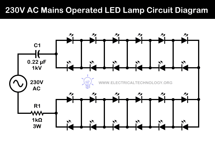
Working on 230V:
The C1 capacitor reduces the voltage to a safe operating level for the LEDs. The R1 resistor, connected in parallel with C1, acts as a protective component, and discharge stored energy and limit the excessive current. The circuit is capable of handling voltage spikes and surges. The 24 LEDs in this design consume approximately 15W, which is capable to provide sufficient illumination and makes it an ideal, powerful LED-based night lamp.
Operating on 120V
If you plan to operate this circuit on a 120V, 60Hz AC mains supply, replace C1 with a 0.68 µF (250V) polyester capacitor. Similarly, reduce R1 to 220 Ω, ½ W. Ensure the use of 3.2V, 25 mA bright LEDs.
Modifications to the Circuit:
- For 100 LEDs (connected back-to-back as shown above): Reduce R1 to 220 Ω, 1W and C1 to 0.47 µF / 400V.
- For 50 LEDs (connected back-to-back as shown above), lover the value of R1 to 220 Ω, ¼W or ½W and C1 to 0.47 µF / 400V.
- With 0.1 µF, you can connect one pair of LEDs (back-to-back).
- By reducing R1 to 220 Ω, ¼ W, the power consumption can be further lowered, which is ideal for night lamp applications.
- Stay safe: Please be careful while working on live circuits. The author will not be liable for any damage or loss(es) while practicing these circuits.
Good to Know:
- It is recommended to assemble this circuit on a general-purpose PCB.
- White LEDs are preferred for higher luminosity in this application.
- This transformer-free circuit is only designed for 230V AC supply. Do not connect to the direct DC supply.
Circuit 2: Automatic 120V Super Bright LED Night Light
Components
- Input = 120V – 60HZ AC Supply
- R1 = 1 Mega Ω Resistor
- R2 = 5.6Ω – 1 Watt
- R3 = 820kΩ
- R4 = 100kΩ – Photocell
- C1 = 0.68µF /400V (Polyester Capacitor)
- C2 = 4.7µF or 10V µF (Polyester)
- D1 = 1A, 400V – 4 No’s of 1N4007 Diodes (Full Wave Bridge Rectifier)
- D2 = Zener Diode – 4754
- D3 = Zener Diode – IN4744
- Q1 = Transistor – ZVN 2106 (N-channel FET)
- LED = 10 LEDs
Circuit Diagram
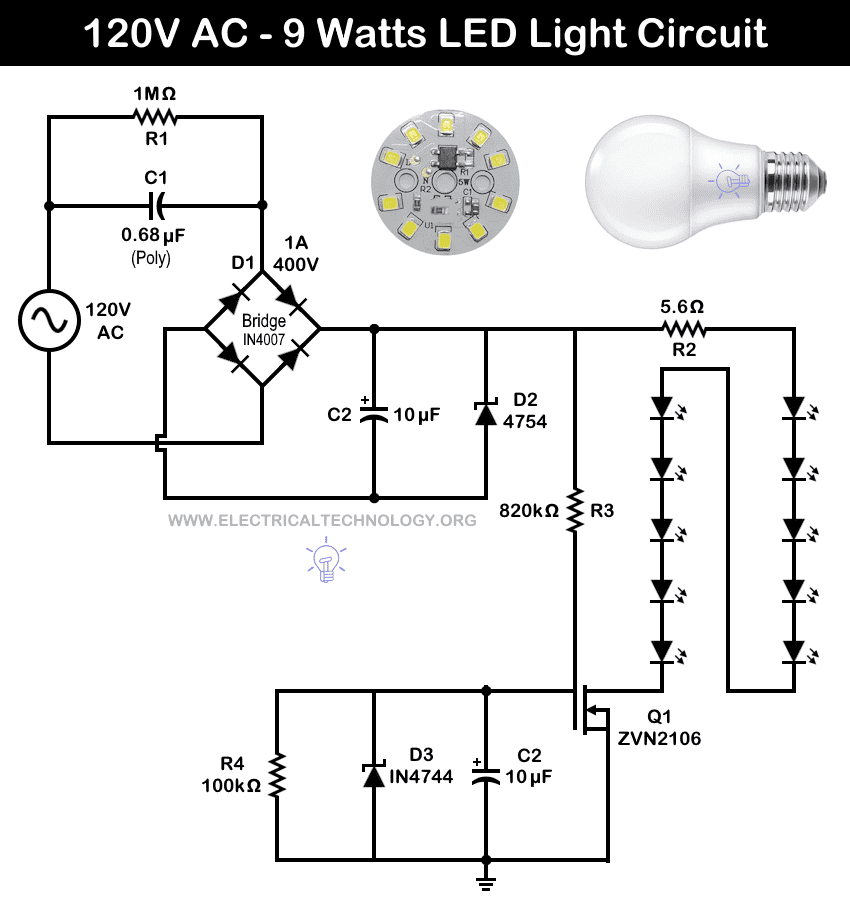
Operation of the Circuit
This super-bright LED night lamp is designed to operate directly from a 120V AC mains supply. In this circuit, the capacitor C1 and resistor R1, connected in parallel, form a voltage and current-limiting network for protection.
The full-wave bridge rectifier (D1) converts the AC supply into DC. Capacitor C2 filters the pulsating DC, while D2 limits the peak voltage across C1 during LED switching and helps regulate the DC voltage.
An additional feature of this circuit is the N-channel FET (Q1), which automatically switches OFF the lamp when sufficient ambient light is detected. The photocell is set to a value of 100 kΩ for full brightness. When the photocell resistance drops below 100 kΩ (due to increased light), the circuit switches off the LEDs.
In operation, ten white LEDs connected in series produce high brightness when powered from the 120V AC supply.
Circuit 3: 230V Ultra Bright LED Night Light
This is the same but modified version of the circuit to operate on 230V AC supply shown above in circuit 2 for 120V.
Components
- Input = 230V – 50HZ AC Supply
- R1 = 470k Ω – 0.25 Watt Resistor
- R2 & R3 = 100 Ω – 0.5 Watt Resistor
- C1 = 1µF /400V (Polyester Capacitor)
- C2 = 10µF /160V (Polyester Capacitor)
- D1 = 1A – 400V Full Wave Bridge Rectifier – 4 No’s of 1N4007 Diodes
- LED = 24 White Color LEDs (50mA)
- Output = 15 Watts
Circuit Diagram:
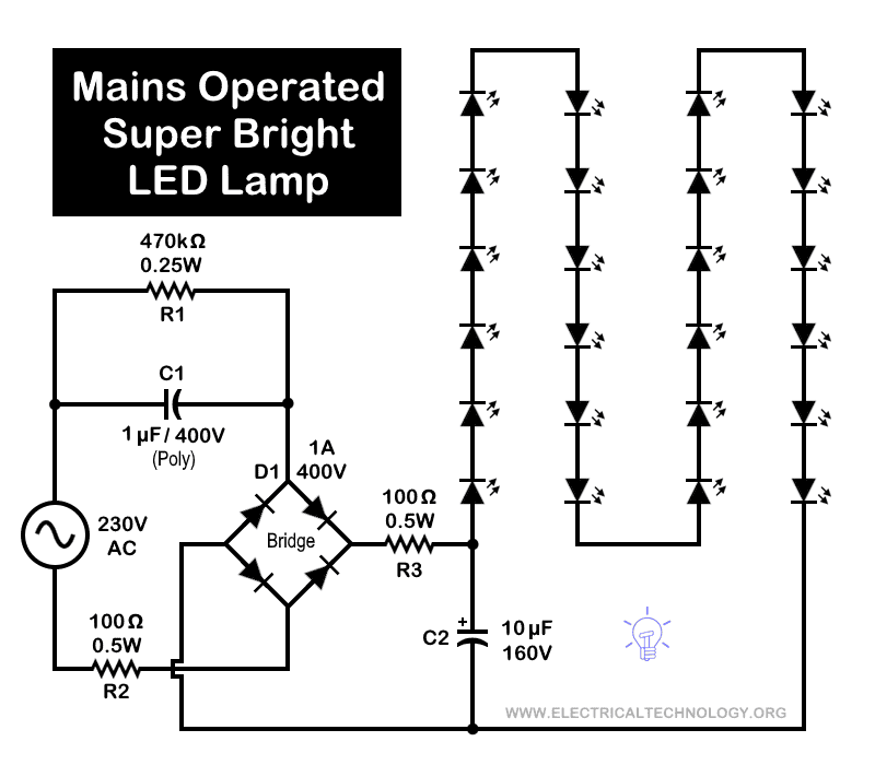
Working of the Circuit
During this modification, the automatic ON/OFF section of the circuit has been removed. It means, the lamp will now be operated manually on a 230V AC supply.
The operation is the same as described earlier for Circuit 2, except for a few component changes listed in the components required section. In this version, 24 super-bright 50 mA LEDs are used instead of the previous 10 LEDs.
The circuit has been tested and provides illumination that is well above the level of a typical 15W tube light or CFL bulb. Therefore, this uniformly illuminated night lamp, based on a simple circuit design, serves as an excellent alternative to more complex circuits.
Circuit 4: 230V AC LED Night Bulb
Internal Components
- R1 = 1 Mega Ω Resistor
- R2 = 560Ω – 1 Watt Resistor
- C1 = 0.22µF /400V (Polyester Capacitor)
- C2 = 35V DC Capacitor
- D1 = 4 No’s of 1N4007 Diodes (Full Wave Bridge Rectifier)
- LED = 16 LEDs, Each Rated at 3V DC
Circuit Diagram:
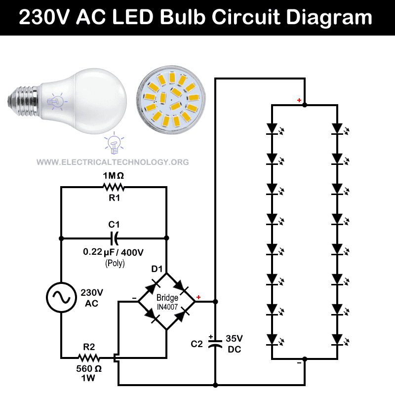
Operation:
This circuit operates by dropping the 230V AC mains voltage to 24V AC. The 0.22µF series polyester capacitor acts as a reactive impedance that limits the current. This limited current then powers the LED string, which naturally stabilizes around 24V DC according to the LED’s forward voltage. The 1 MΩ resistor in parallel with capacitor is used to safely discharge the stored energy when the circuit is switched off. In addition, the 560 Ω resistor is used for short-circuit protection.
The reduced AC voltage is converted to DC through a full-wave bridge rectifier and filtered by an electrolytic capacitor. This way, it provides a stable 24V DC supply for the LED array. Two parallel strings of eight 3V LEDs each are powered, matching the total forward voltage to the supply while sharing current. As a result, we have efficient and bright illumination.
These kind of circuits are mostly used in commercial LED light lamps used in household applications.
Circuit 5: 230V Brighter LED Light
Components:
- Input: 230V AC
- R1 = 110k Ω Resistor
- R2 = 56Ω – 1 Watt Resistor
- C1 = 1µF /400V (Polyester Capacitor)
- C2 = 680µF – 50V
- D1 = 4 No’s of 1N4007 Diodes (Full Wave Bridge Rectifier)
- LED = 12 White LEDs
Circuit Diagram:
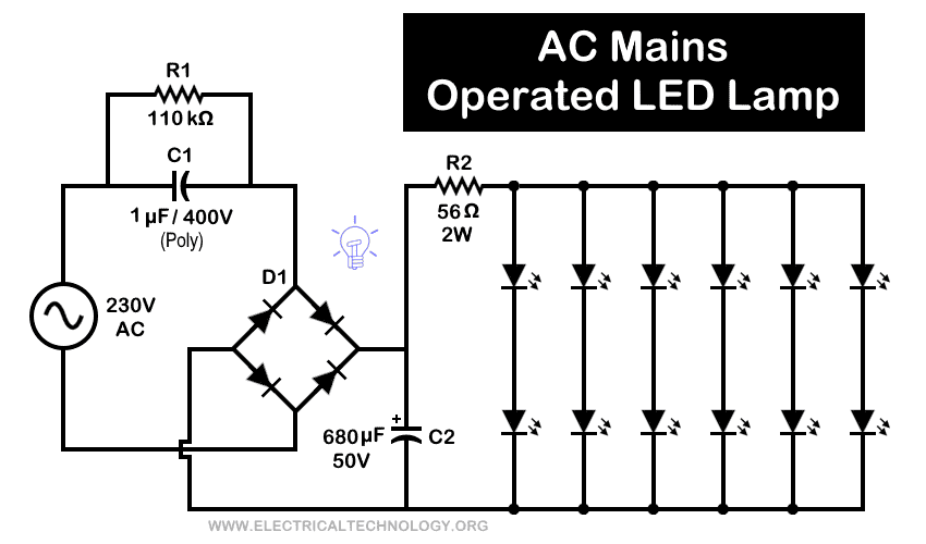
Operation:
This is another basic, cost-effective, yet bright LED circuit based on a transformerless AC mains power supply. When the mains supply is connected, capacitor C1 and resistor R1, connected in parallel, reduce the voltage to a safe level.
The bridge rectifier then converts the reduced AC voltage into DC, while capacitor C2 filters the pulsating DC into a stable DC output. Resistor R2 limits the current to match the LEDs’ current rating.
In this compact, lightweight, and efficient circuit, 12 bright white LEDs connected in series strings produce bright illumination when powered from a 230V AC supply.
Bonus Circuit 6: 230V Mains Operated Blinking LED Circuit
Components
- Input = 230V – 50HZ AC Supply
- R1 = 47k Ω – 3 Watt Resistor
- R2 = 270 Ω
- D1 = Diode – IN4007
- D2 = LED
- C1 = 47µF /50V (Polyester Capacitor)
- DIAC = DB3
Circuit Diagram:
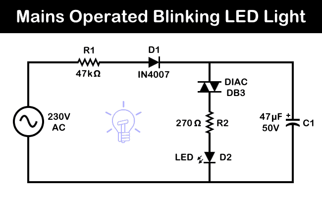
Working of the Circuit
This is a very basic blinking LED circuit designed to operate on a 230V AC mains supply. When the mains power is switched ON, capacitor C1 begins charging through resistor R1 and diode D1. Once the voltage across C1 exceeds 32V (the breakover voltage of the DIAC DB3) the DIAC conducts, causing the LED to flash.
At the same time, C1 discharges through the LED, completing the flash cycle. This process repeats continuously, producing a blinking effect. The blinking rate of the LED depends on the values of R1 and C1.
Warning:
- Exercise extreme caution when handling this circuit, as 230V AC is potentially lethal.
- Stay safe! The author will not be liable for any damage or loss while practicing these circuits.
Related LED’s Circuits and Projects:
- LED Light Bulb Circuit – 230V / 120V Mains Operated LEDs
- Emergency LED Light Circuit – DP-716 Rechargeable 30 LED’s Lights Schematic
- How to Make a Simple LED Flashing Circuit using 555 Timer IC
- 1 Minute, 5 Minute, 10 Minute and 15 Minute Timer Circuit Diagram
- Automatic Night Lamp Using Arduino
- LED Roulette Circuit Diagram using 555 Timer & 4017 Counter
- USB Propeller LED Fan Clock – Circuit Diagram & Project Code
- How to Calculate the Value of Resistor for LED’s & Different Types of LED Circuits
- LED Resistor Calculator – Required Value of Resistor for LED’s Circuit
- How to Make Christmas LED & Bulb Blinking Light String Circuit at Home
- Automatic Street Light Control Circuit using LDR & Transistor BC 547
- PCB Design of LED Flasher Circuit. Step by Step
-
 How to Wire a Smart Switch Companion with a Smart Switch
-
 Motor Capacitor Calculator – Calculate Fan Capacitor Value
-
 Can You Install Breakers and Switches on Neutral Conductor
-
 Can You Use a 2-Pole Breaker Instead of a 1-Pole Breaker
-
 What is the Life Expectancy of a Circuit Breaker?
-
 Wiring Z-Wave Smart Switch, Dimmer & Fan Speed Controller