1 Minute, 5 Minute, 10 Minute and 15 Minute Timer Circuit Diagram
1 to 15 Minute Timer Circuit Diagram, Working and Applications
In the era of technologies, everyone is taking the help of machines to simplify their life. Timer circuits ease your day to day tasks in many ways by initiating or doing it in a definite time interval. In other words, if you are looking for an automated device to work for a certain time period and switch off after the desired time then this Timer Circuit is the best choice to opt.
In this project, we are using 555 Timer IC to create various timer circuit like 1 min timer circuit, 5 min timer circuit, 10 min timer circuit, and 15 min timer circuit. Here, with the help of the 555 timer IC, we are eliminating the need of manually switching ON or OFF the device. Also, 555 Timer is used to generate an oscillating pulse. Which means that the output pin3 of 555 Timer IC is in “OFF” condition for some time and again comes in “ON” condition after a pre-set time interval. We can use this oscillating behavior of 555 Timer IC to create the timer circuit of different time delays. To create the timer circuit for the desired time interval, simply change the value of the resistor R1 or Capacitor C1.
We can use the different timer circuits of a different time delay to operate an alarm, a device, motors, etc. at a certain time interval. The main role in this circuit is played by the 555 Timer IC. We will be discussing all the four-timer circuits (1Min, 5Min, 10 Min and 15 Min timer) one by one throughout this article. Before that let’s take a brief idea of the 555 Timer IC.
555 Timer IC
555 Timer IC is used in timer, pulse generation, and oscillator applications. 555 Timer IC can be mainly configured in three different states namely A-Stable multi-vibrator, Mono-Stable multi-vibrator, and Bi-Stable multi-vibrator.
Let’s see the internal circuitry of the 555 Timer IC to get a better idea of its working principle:
There are three 5K ohm resistors connected together internally. This produces a voltage divider network at Pin 8 and Pin 1. The two comparators produce an output voltage that depends upon the voltage difference at their input. The voltage difference is determined by the externally connected RC network. The output of both the comparators is connected to the input of flip-flop to produce either a “High” or “Low” logic output based on the states of Input. The output from flip flop can be used to control a high current output switching stage to drive the connected load producing High or Low level at the output pin.
- Related Post: Simple Touch Sensitive Switch Circuit using 555 Timer
Pinouts of 555 Timer IC:
- Pin 1- Ground
- Pin2- Trigger
- Pin3- Output
- Pin4- Reset
- Pin5- Control voltage
- Pin6- Threshold
- Pin7- Discharge
- Pin8- Power Supply (4.5- 15 V)
Applications of 555 timer IC:
555 Timer IC is a useful precision timing device produces single pulses or as an oscillator producing a string of stabilized waveform of any particular duty cycles.
- It can be used in one-shot or delay timers to produce a time delay.
- It can be used in LED or flash lamps to turn the lamp on for a specified time.
- IT can be used in tone generation or logic clocks
- It can be used in power supplies and converters etc
- Related Project: PCB Design of LED Flasher Circuit using 555 Timer. Step by Step
Components Required
Collect the below-mentioned components to design the timer circuit of different time duration:
- 555 Timer IC
- LED
- Capacitor (1000 μF)
- Variable resistor
- Push button
- Resistor
- Power supply
- Connecting wires
- Related Project: Clap Switch Circuit Using IC 555 Timer
Circuit Diagram
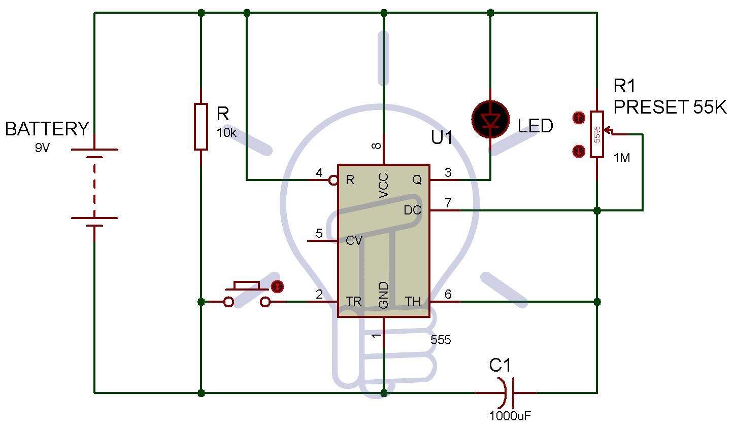
The above circuit diagram is for the 1-minute timer circuit. For 5 min, 10 min and 15 min you just have to change the resistor value (R1).
1 Minute Timer Circuit:
We have to configure 555 Timer in Mono-Stable mode to build a timer. The 555 Timer starts timing when switched ON. After one minute of time duration, the LED will automatically turn ON. Generally, the time duration for which Pin3 of 555 Timer IC will remain high, can be derived by the given formula:
T=1.1*R1*C1
As discussed above, we have to change the value of the capacitor or resistor. Now, for making a 1-minute timer circuit, we can calculate the value of the resistor by using the above formula:
60 sec = 1.1 x R1 x 1000 μf
R1 = 60 / (1.1 x 1000 μF)
R1 = 55K
Hence, set the value of potentiometer to 55k and your timer will be set for 1 minute. Now you can easily use the above formulae to determine the value of the resistor in 5 Minute, 10 Minute and 15 Minute timer circuit.
Note: You can also use the formula to make a timer circuit by changing the capacitor value and make the resistance value constant.
- Related Project: Traffic Light Control Electronic Project using 555 Timer
5 Minutes Timer Circuit:
Similarly, in the 5-minute timer circuit, we will be using the above formula to get the exact resistance of the resistor.
T= 1.1* R1*C1
Now, the time is 5 minutes and will be equal to (5 x 60) seconds. The value of the capacitor will remain same for all the timer circuit.
Here,
T= 5*60
C1= 1000 μF
5*60= 1.1*R1*1000 μF
Therefore, R1= 272.7 k ohm
Hence, to design a 5-minute timer circuit, change the resistor value with 272.7 k ohm. And, after 5 Minute the LED will be turned ON. As soon as the Pin2 of 555 Timer IC is triggered, the timer will start timing and LED will be turned OFF. After 5 Min of time duration, pin3 of 555 Timer IC will again become low and the LED will be turned ON.
Related Project: Automatic Street Light Control System using LDR & Transistor BC 547
10 Minutes Timer Circuit:
Again, as discussed above, you only have to change the resistor value of R1 to design the 10 Min timer circuit. Below is the calculation for finding the value of the resistor:
T= 1.1* R1*C1
Now, the time is 10 minutes and will be equal to (10 x 60) seconds. The value of the capacitor will remain same for all the timer circuit.
Here,
T= 10*60
C1= 1000 μF
10*60= 1.1*R1*1000 μF
Therefore, R1= 545.4 k ohm
In this case, Pin3 of the 555 Timer IC will again become low and the LED will be turned ON after 10 Min of time duration.
- Related Project: Water Level Indicator Circuit Diagram- using BC547 Transistor
15 Minutes Timer Circuit:
For setting the timer to 15 minutes, change the value of resistor R1, using the below formula:
T= 1.1* R1*C1
Now, the time is 15 minutes and will be equal to (15 x 60) seconds. The value of the capacitor will remain same for all the timer circuit.
Here,
T= 15*60
C1= 1000 μF
15*60= 1.1*R1*1000 μF
Therefore, R1= 818.2 k ohm
So, by replacing the resistor value to 818.2k ohms the LED will be turned ON after 15 Min of time duration.
- Related Electron Project: What is ATMega Microcontrollers & How to Make an LED Project with it?
Working of Timer Circuit
555 Timer IC works excellent for generating the time delay for a particular interval. However, to generate the time delay of more than 20 Minutes of time duration, 555 Timer is not that much suitable.
Here, we have used the reverse logic with LED. Which means that whenever the output Pin3 of 555 Timer IC is Low, the LED will be ON.
Similarly, the LED will be OFF when the output Pin3 of 555 Timer IC is set to High. In the above calculations, the LED will be turned ON after the calculated time duration. The output Pin3 of 55 Timer will be Low initially. AS soon as the 555 Timer IC is triggered, it will start timing and the LED will be turned OFF. After the pre-set time delay, the LED will turn on again as the Pin3 will again set to Low.
Above we have calculated the resistor value for different timer circuits such as 1 min, 5 min, 10 min, and 15 min.
Application
The timer circuits of different time delay are of great use in real life to automate an action to be done at the desired time without the involvement of human beings. Browse the list of applications of timer circuit in day to day life.
- It can be used in motor vehicles to control the wiper speed by setting a definite time for the wiper to be in action
- It can be used in devices to produce alarm after a certain time interval automatically.
- It can be used in lamp dimmer to glow the LED automatically after a certain time interval.
- It can be used in the circuit where you want to produce a cyclic operation
- In air-cooler, there are pump waters to the mat continuously. We can use the timer circuit to Switch OFF the pump when mats are wet and to switch ON again when the mats get dry.
Bottom Line
In the above discussion, we have designed the timer circuits of 1Minute, 5Minute, 10 Minute and 15 Minute time delay using 555 Timer IC. Timing devices are of great use in day to day life and are very easy to design. We can rely on a 555 Timer IC for generating the time delays of 15-20 Minutes. We hope that you have got a good knowledge of 555 Timer IC and different timer circuits using the same. Now, you can easily design the different timer circuits of 1Minute,5 Minute,10 Minute and 15 Minute using 555 Timer IC with ease.


Such types of timers may only be suitable for child’s plays because no constancy of timing can be achieved with such RC circuits.
It would be an extremely vague to represent the timing characteristics of such circuit by ” T = 1.1 * R * C “. As a matter of fact the non-precise and crude characteristics of Electrolytic capacitors of higher MF. values do not allow those to be used in such applications faithfully. Drift in their capacities due to constant ageing, internal leakage factor, temperature, working voltage etc. makes those non suitable for any precision application. Their result is expected within a broad spectrum of +/- 20%. Of course their results could be utilized for non precise timings in 10 – 30 seconds range while using lower values of resistances. Also that, there is no compulsion for using a 555 ic, just a Darlington along with a Zener could be used with similar R C circuit for achieving the results – Rajiv Mohan
Can anyone give me the circuit diagram of autoon 10min and auto off 10 minutes