How to Install a 2-P, 20A – 240V GFCI Breaker for Branch Circuits
2-Pole GFCI Breaker
A two-pole GFCI (Ground-Fault Circuit Interrupter) breaker is used to provide both overcurrent protection and ground-fault protection for 240V loads or 120/240V multi-wire branch circuits (MWBCs). Typical applications include electric water heaters, hot tubs, spas, HVAC equipment, pool pumps, and certain receptacle circuits in wet or outdoor locations as per NEC requirement.
Unlike standard 2-pole breakers, a 2-pole GFCI breaker continuously monitors the current balance between ungrounded (hot) conductors and the neutral conductor. If an imbalance exceeding 5 mA is detected, it indicates there is a current leakage to ground, therefore, the GFI breaker trips instantly to reduce the risk of electric shock.
A GFCI breaker differs from a standard breaker. It protects 240V circuits (two 120V hot conductors supplied from both Hot 1 or Hot 2) and offer protection against both overcurrent and ground faults.
A 2-P GFCI requires a neutral connection to the breaker, that’s why it has a built-in white pigtail wire which connects to the neutral busbar in the main panel. In case of 120/240V circuits (such as NEMA 14 series e.g. NEMA 14-50), the load side neutral is connected to the GFCI, not to the neutral busbar in the main panel. If load side neutral doesn’t required in a 240V circuit (such as NEMA 6-20 receptacle), only the white pigtail connects to the neutral busbar. This way, a GFCI protects the entire branch circuit, not just individual receptacles. In short, a GFCI provides both overcurrent and ground-fault protection.
A 2-P GFCI breaker requires a neutral connection to operate properly. For this reason, it is equipped with a built-in white pigtail conductor, which must be connected to the neutral busbar in the main panel.
In 120/240V circuits (such as those supplying NEMA 14-series receptacles (e.g., NEMA 14-50), the load-side neutral conductor must be terminated on the GFCI breaker’s neutral terminal, not on the panel’s neutral busbar. This allows the GFCI to monitor the current balance between the ungrounded (hot) conductors and the neutral conductor.
For 240V circuits that do not require a neutral (such as those supplying a NEMA 6-20 receptacle) the only neutral connection is the white pigtail from the GFCI breaker to the neutral busbar. No load-side neutral conductor is used in this case.
With this wiring method, the GFCI breaker provides ground-fault protection for the entire branch circuit rather than for individual receptacles only. In short, a GFCI breaker provides both overcurrent protection (as a circuit breaker) and ground-fault protection for personnel.
Characteristics:
- Number of Poles: 2-pole – connects to two lines (L1 & L2), i.e. both hot conductor (black and red). Both lines are mechanically and electrically linked together.
- Voltage: Operates on and protects 240V branch circuits. (Line-to-Line).
- Amperage Rating: Commonly available in 15A, 20A, 25A and 30A.
- Wiring: Two hot conductors from the breaker, a ground wire (+ a neutral if required) from ground/neutral busbar connects to the branch circuit in a 240V supply. The built-in white pigtail on the GFCI breaker always connects to the neutral busbar in the main panel.
- Operation: Trips when there is an overload, short circuit, or ground-fault on a single or both hot conductor(s).
- Application: Used as per NEC requirement for standard lighting, outlets, receptacles, sockets and small to medium load appliances located in outdoor or wet areas.
NEC Requirements for GFCI
NEC 210.8(A) requires ground-fault circuit-interrupter (GFCI) protection for 125-volt through 250-volt, single-phase, 15- and 20-ampere receptacles installed in specific locations. These locations include, but are not limited to, bathrooms, garages, outdoor areas, basements, kitchens, laundry areas, and similar spaces as identified by the Code.
In accordance with NEC 210.8(A), both dwelling and non-dwelling units must provide GFCI protection for all 120/240-volt outlets and receptacles installed in the locations listed in 210.8(A)(1) through 210.8(A)(11). This requirement applies to single-phase branch circuits rated 150 volts or less to ground.
Additionally, GFCI protection is required for various occupancies and equipment as specified throughout the NEC. Relevant Code sections include, but are not limited to, Articles 210.8, 406.3, 424.44, 426.28, 427.22, 511.12, 517.17, 517.20, 525.23, 530.44, 547.28, 555.35, 620.6, 625.54, 680.5, 680.21, 680.22, 680.23, 680.27, 680.32, 680.43, 680.44, 680.51 through 680.59, 680.62, and 680.71.
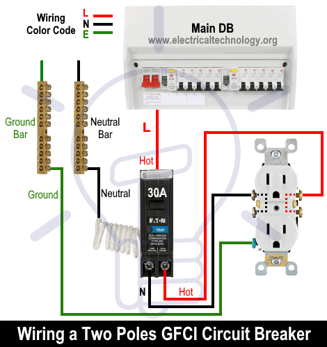
Wiring a Two-Pole GFCI Breaker in a 120/240V Panel
To install or replace a 2-P GFCI breaker in a 120/240V single-phase panelboard, follow the following simple steps.
Step 1: De-Energize the Panel: Switch off the main disconnect or main breaker and verify the absence of voltage using a non-contact tester.
Warning: Never touch the service entrance conductors or main breaker lugs as they remain energized even when the main breaker is OFF.
Step 2: Install the Breaker: GFCI breakers are manufacturer-specific such as Square D – Q/Homeline or BR/CH etc. Ensure the breaker is listed and approved for the panelboard model. When sure, snap the breaker onto both bus bars so that it engages L1 and L2.
Step 3: Connect the wires as follow:
- Hot 1 (L1) as black wire to the breaker terminal 1
- Hot (L2) as red wire to the breaker terminal 2
- Load Neutral as white wire to the Neutral terminal on the GFCI breaker (if present)
- Breaker white coiled pigtail to the neutral busbar in the panel
- Equipment ground (EGC) as green or bare copper conductor to the ground busbar in the panel
Good to Know:
- Strip about ½ inch (≈12 mm) of insulation from grounded and ungrounded conductors for termination.
- The tightening torque for termination is 40.7 lbf.in (4.6 N.m) 0.006…0.03 in2 (4…20 mm2) or in accordance to the panel / breaker marking.
- Do not connect GFCI breaker to more than 250 ft. (76 m) of load conductor for the total one-way run.
- A GFCI-protected circuit neutral must never terminate on the neutral bus.
- Neutral and ground bonded only in the main panel. In case of subpanel, EGC and Neutral should be connected to corresponding isolated busbars.
Step 4: Test and Reset: Replace the panel cover and restore the power. To test and inspect;
- Press the TEST button on the GFCI breaker. The breaker must trip immediately.
- Reset the breaker and verify proper operation of the load.
A 2-Pole GFCI breaker can be installed on a 120/240V AC single-phase, 3-Wire system, the 120/240V AC portion of a 240/120V, 3-Phase, 4-Wire system (High Leg), or on a 208Y/120V, 3-phase, 4-Wire system.
For a 2-Pole GFCI breaker, a load neutral is not required on 240V circuits. However, the white line neutral (pigtail) must be connected to the panel neutral for the device to function properly.
For 120/240V circuits where Neutral is required, the load neutral should be connected from the neutral terminal of GFCI, not from the neutral busbar.
Wiring 240V, 2-Pole GFCI Breaker without Neutral
In the given wiring diagram, a 15A, 240V, two-pole GFCI breaker is installed to protect a 15A, 250V receptacle (NEMA 6-15R). In accordance with NEC Table 310.16, the suitable conductor size for a 15A branch circuit supplying a NEMA 6-15R receptacle is #14 AWG copper. The equipment grounding conductor (EGC) must also be #14 AWG, as specified in NEC Table 250.122.
Click image or open in a new tab to enlarge
Wiring 120/240V, 2-Pole GFCI Breaker With Neutral
In the given wiring diagram, a 50A, 120/240V, two-pole GFCI breaker is wired to protect a 50A, 120/250V receptacle (NEMA 14-50R). As the circuits needs a neutral wire, hence, the load side neutral is connected from the neutral terminal of the GFCI, not the neutral busbar in the main panel.
Click image or open in a new tab to enlarge

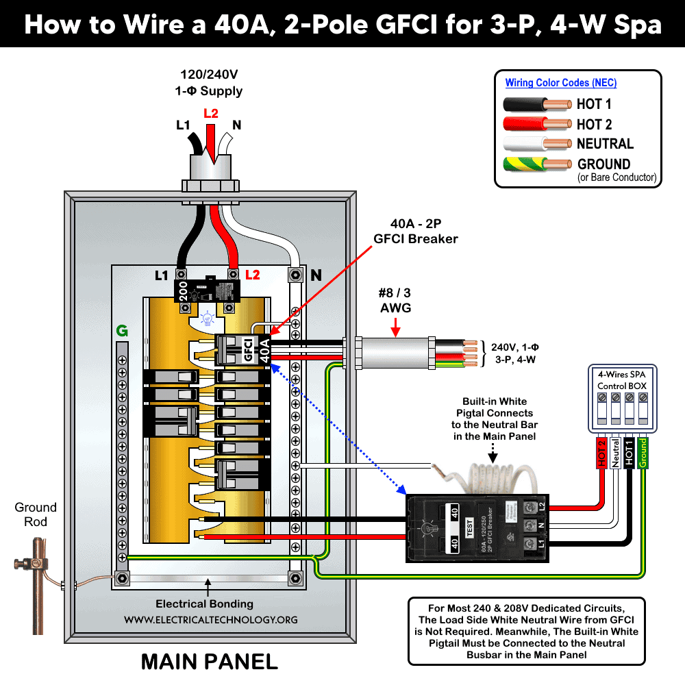
Similarly, the following wiring diagram shows how to install a 40A, 2-Pole GFCI breaker in 120/240V spa panel for hot tub. As mentioned before, the load side white neutral wire from GFCI is not required for most 240V and 208V dedicated circuits. If needed as per circuit requirement, the load side neutral is connected from the GFCI neutral terminal. Meanwhile, the built-in white pigtail must be connected to the neutral busbar in the main panel.
Click image or open in a new tab to enlarge
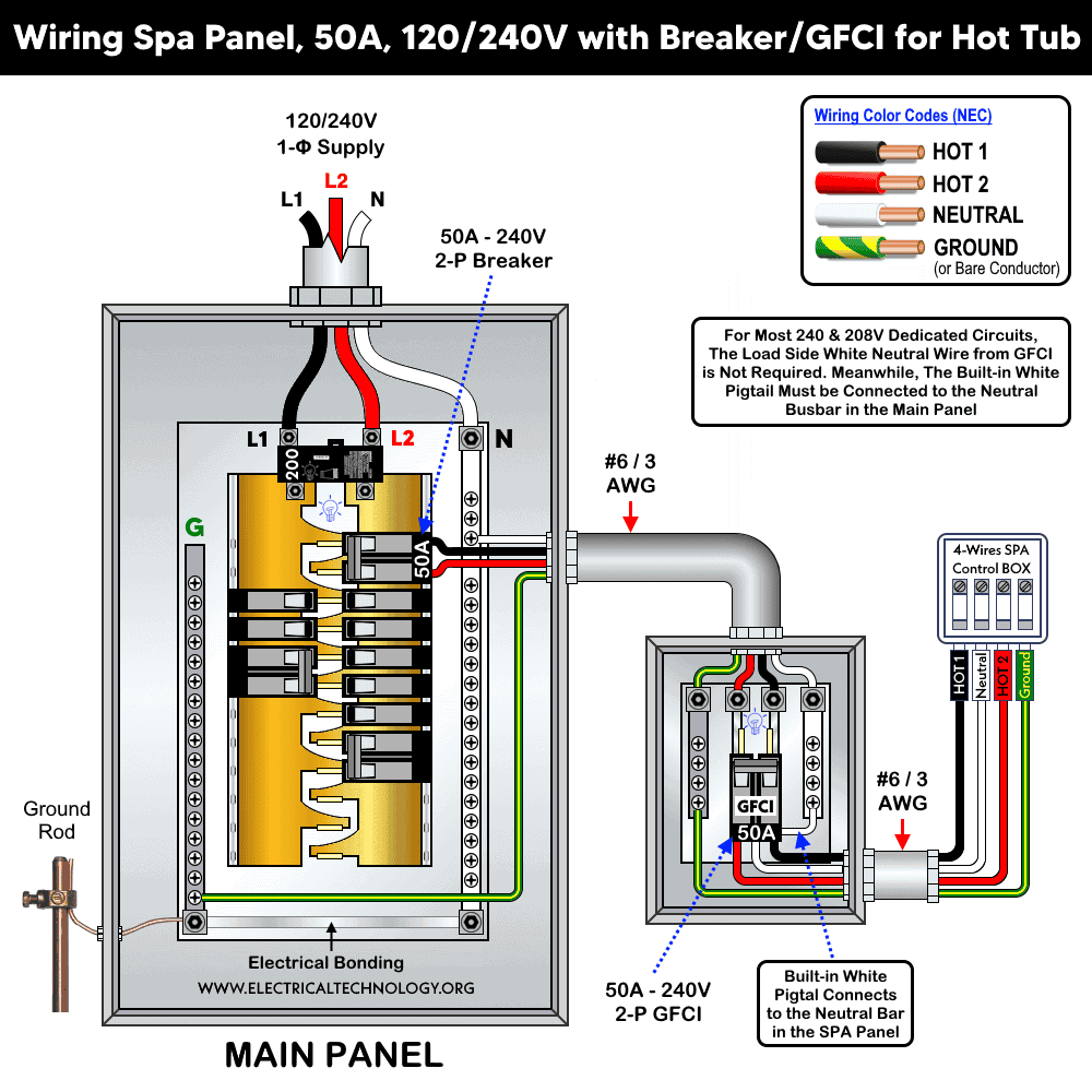
Moreover, the following wiring diagram illustrates the installation of a spa panel box containing a 50A, 120/240V, two-pole GFCI breaker. The spa panel is supplied downstream from a standard 50A, two-pole breaker installed in the main 120/240V panel.
Click image or open in a new tab to enlarge
Except for the 20A example shown, a 2-pole GFCI breaker may be installed for other circuit ratings and may supply various NEMA receptacles used on 240V or 120/240V single-phase systems as as:
- Wiring a 2-pole GFCI breaker for 15A – 250V outlet
- Wiring a 2-pole GFCI breaker for 20A – 250V outlet
- Wiring a 2-pole GFCI breaker for 20A – 125/250V receptacle
- Wiring a 2-pole GFCI breaker for 30A – 250V receptacle
- Wiring a 2-Pole GFCI breaker for 30A – 125/250V receptacle
- Wiring a 2-pole GFCI breaker for 50A – 250V receptacle
- Wiring a 2-pole GFCI breaker for 50A & 40A – 120/240V Spa & Hot tub
- Wiring a 2-pole GFCI breaker for 50A – 125/250V receptacle
- Wiring a 2-Pole GFCI breaker for 60A – 125/250V receptacle
Good to Know:
- The voltage between L1 and L2 i.e. two Hots e.g. Hot 1 and Hot 2 = 240V phase to phase.
- For 240V load without Neutral, the Neutral terminal (if present) from the breaker is unused (such as NEMA 6-15. 6-20 receptacles).
- For 120/240V load with Neutral, the Neutral terminal from the breaker is connected to the load neutral (not to the neutral busbar in the main panel) such as NEMA 14-30. 14-50 receptacles.
Instructions, Precautions & Codes
- As per NEC Table – 310.16, Table – 210.24(1) and NEC 240.4(D)(4), the suitable wire size is 12 AWG copper (or #10 AWG aluminum) to use with a 20A outlet and protected by a 20/120V GFCI/Breaker.
- As per NEC Table 250.122, use the same #12 AWG copper for ground (EGC) wire size.
- The correct size of breaker is 2-pole, 20A circuit breaker or GFCI for a 20A-125V outlet – NEC 210.21(B)(2).
- For a 2-pole, 20A GFCI circuit, you may use NM-B (Romex) for indoor and dry locations, UF-B for outdoor or underground runs, and THHN/THWN conductors when installed in conduit.
- A two-pole 20A GFCI/breaker can be used for 16A continuous load (which lasts 3 or more hours) and maximum 20A non-continuous load – 210.19(A), 210.20(A), 215.2(A), 215.3, and 230.42(A).
- A 2-pole, 20-amp breaker/GFCI at 240 volt can handle non-continuous load of 4,800 watts (20A × 240V). For continuous use, limit the load to about 3,840 watts (80% of 1,800W).
- Do not use 20A outlet on 15A circuit breaker. If more than one receptacle on the same circuit, you may allowed to use 15A outlet on 20A circuit breaker. In other words, It is code to use 15A outlet on 20A breaker (NEC 210.21(B)(2)), but it is not allowed to use 20A outlet on 15A breaker.
Warning:
- Make sure to disconnect the power supply by switching OFF the breaker in the main panel before doing any electrical work.
- If you are unsure, contact a licensed electrician to do it according to the local area codes.
- The author will not be liable for any losses, injuries, or damages from the display or use of this information or if you try any circuit in wrong format. So please! Be careful because electricity is too dangerous.
Resources:
Standard Breakers & GFCI Breakers Wiring Installations
- How to Wire a 1-Pole GFCI
- How to Wire a 2-Pole GFCI … You are Here
- How to Wire a 3-Phase, 3-Pole GFCI
- How to Wire a 1-Pole Breaker
- How to Wire a 2-Pole Breaker
- How to Wire a 3-Pole Breaker
- How to Wire a Tandem Breaker
- How to Wire GFCI Circuit Breakers
- How to Wire an AFCI Breaker
Sizing Breakers, Wires, and Panels
- How to Size a Circuit Breaker?
- How to Size a Breaker and Wires in AWG with EGC for Load?
- How to Find the Proper Size of Wire & Cable In Metric & Imperial Systems
- How to Size a Load Center, Panelboards and Distribution Board?
- How to Determine the Right Size Capacity of a Subpanel?
- How to Find the Right Wire Size for 100A Service 120V/240V Panel?
- How to Size Service-Entrance Conductors and Feeder Cables?
- How to Size Feeder Conductors with Overcurrent Protection
- How to Size a Branch Circuit Conductors with Protection?
- How to Size Equipment Grounding Conductor (EGC)?
- How to Size Grounding Electrode Conductor (GEC)?
- How to Size Motors FLC, HP, Voltage, Breaker Size and Wire Size
- What is the Correct Wire Size for 100A Breaker and Load?
- What is the Right Wire Size for 15A Breaker and Outlet?
- What is the Suitable Wire Size for 20A Breaker and Outlet?
General Outlets and GFCI/AFCI Receptacles Wiring
- How to Wire an Outlet Receptacle? Socket Outlet Wiring Diagrams
- How to wire a GFCI Outlet?
- How to Wire GFCI Combo Switch and Outlet
- How to Wire an AFCI Combo Switch
- How to Wire an AFCI Outlet?
- How to a Wire 3-Way Combination Switch and Grounded Outlet?
- How to Wire Combo Switch and Outlet? – Switch/Outlet Combo Wiring Diagrams
- How to Wire a 15A – 120V Outlet – NEMA 5-15 Receptacle
- How to Wire a 20A – 120V Outlet – NEMA 5-20 Receptacle
- How to Wire a 15A – 240V Outlet – NEMA 6-15 Receptacle
- How to Wire a 20A – 240V Outlet – NEMA 6-20 Receptacle
- How to Wire a 50A – 125/250V Outlet – NEMA 14-50 Receptacle
Switches Wiring
- How to Wire Single Pole, Single Throw (SPST) as 2-Way Switch?
- How to Wire Single Pole, Double Throw (SPDT) as 3-Way Switch?
- How to Wire Double Pole, Single Throw Switch? Wiring DPST
- How to Wire Double Pole, Double Throw Switch? Wiring DPDT
- How to Wire Double Switch? 2-Gang, 1-Way Switch – IEC & NEC
- How to Wire 4-Way Switch (NEC) or Intermediate Switch as 3-Way (IEC)?
- How to Wire Auto & Manual Changeover & Transfer Switch – (1 & 3 Phase)
Finding the Number of Breakers/Outlets in a Circuit
- How to Determine the Number of Circuit Breakers in a Panelboard?
- How to Find the Number of Outlets on a Single Circuit Breaker?
- How to Find Voltage & Ampere Rating of Switch, Plug, Outlet & Receptacle
- How to Calculate the Number of Fluorescent Lamps in a Final Sub Circuit?
- How to Calculate the Number of Incandescent Lamps in a Final Sub Circuit?
- How to Determine the Number of Lighting Branch Circuits?
- How to Determine the Number of Branch Circuits? – 3 Ways
- How to Find the Number of Lights on a Single Circuit Breaker?
Main Panels Wiring Tutorials
- How to Wire 120V/240V Main Panel? Breaker Box Installation
- How to Wire 208V/120V, 1-Phase & 3-Phase Main Panel?
- How to Wire 240V, 208V & 120V, 1 & 3-Phase, High Leg Delta Main Panel?
- How to Wire 277V/480V, 1-Phase & 3-Phase Main Service Panel?
- How to Wire a Subpanel? Main Lug Installation for 120V/240V
- Single Phase Electrical Wiring Installation in Home according to NEC & IEC
- Three Phase Electrical Wiring Installation in Home – NEC & IEC
- How To Wire a Single Phase kWh Meter – 120V/240V
- How to Wire a Three-Phase Meter? 120/208/240/277/347/480/600V
General Wiring Installation Tutorials:
- How to Toggle Electric Water Heater Between 120V and 240V?
- How to Wire 120V Water Heater Thermostat – Non-Simultaneous?
- How to Wire 240V Water Heater Thermostat – Non-Continuous?
- How to Wire 3-Phase Simultaneous Water Heater Thermostat?
- How to Wire Twin Timer for 120V/240V Circuits – ON/OFF Delay
- How to Wire ST01 Timer with Relay & Contactor for 120V/240V Motors?
- How to Wire Multifunction ON/OFF Delay Timer for 120V/240V Motors?
- Even More Residential Wiring Installation Tutorials
Related Posts:
- Difference Between Circuit Breaker and GFCI
- Difference Between 1-Pole and 2-Pole Breakers – NEC & IEC
- Should GFCI Protection Be in the Main Panel or Receptacle?
- How Does a Standard Breaker Respond to Electrical Fault?
- Why Doesn’t a Standard Breaker Protract Against Ground Faults?
- How Do GFCI and Standard Breakers Respond to Ground Faults?
- Can you use 15A Breaker on 20A Circuit and Vice Versa?
- Can I Use a 1-Phase Breaker on a 3-Phase Supply & Vice Versa?
- Can I Use a 240V Breaker on a 120V Circuit and Vice Versa?
- Can You use a 15A Outlet on a 20A Circuit and Vice Versa?
-
 How to Wire Smart Scene Controller Switch
-
 How to Install a Home and Away Wireless Smart Switch
-
 Arkansas School Uses Rooftop Solar to Raise Teacher Pay
-
 How to Install a Wire-Free Smart Dimmer Anywhere Companion
-
 How to Wire a Smart Wireless Switch and Anywhere Companion
-
 Wiring a Smart Dimmer Switch Companion with a Digital Dimmer