LED Roulette Circuit Diagram using 555 Timer & 4017 Counter
Flashing LED Roulette Circuit Diagram using 555 Timer & 4017 ICs
There is a casino game and a French word accompanying it called “Roulette”. This circuit resembles the functioning of a Roulette wheel game, hence the name given to it. This circuit consists of a timer IC and a special IC called CD 4017, which is a decade counter.
- Related Post: Simple LED Flashing Circuit using 555 Timer IC
LED Roulette Circuit Diagram
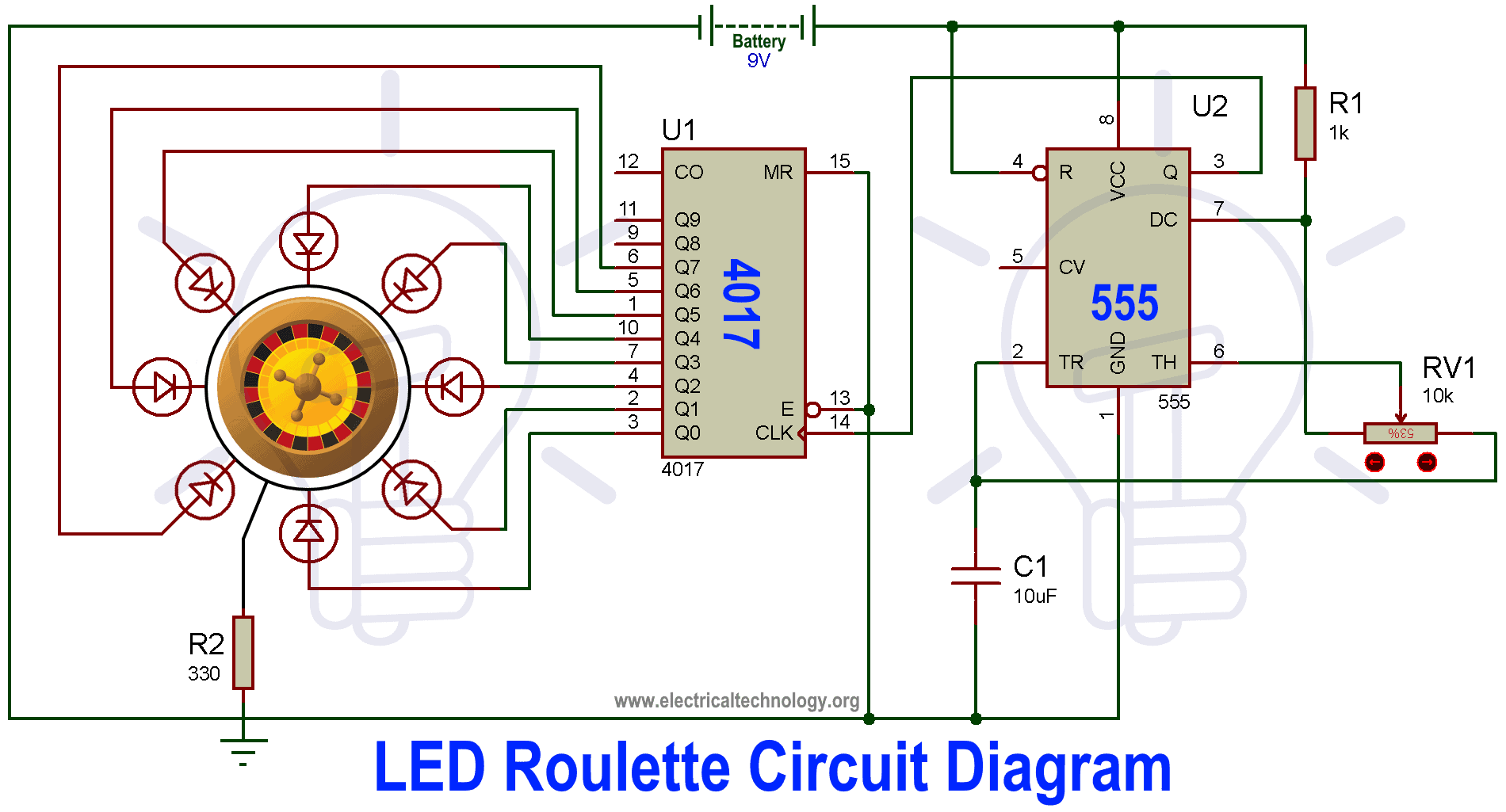
Below is the circuit diagram for the LED roulette circuit.
Components Required
- 555 Timer IC
- Decade Counter CD IC 4017
- 8 Nos of LEDs
- 220Ω, 1kΩ & 10kΩ Resistors
- 10µF Capacitor
- Potentiometer
- 9V Battery to power the circuit
555 Timer IC
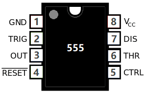
555 timer IC is mainly used for the pulse generation and as an oscillator. The pin diagram of the 555 Timer IC is given below.
| 555 Timer IC | ||
| Pin no. | Pin Name | Purpose |
| 1 | GND | Ground reference voltage |
| 2 | TRIG | Controls output |
| 3 | OUT | Is driven to ~1.7V below Vcc or to ground |
| 4 | RESET | Reset a timing interval |
| 5 | CTRL | Provides access to the internal voltage divider |
| 6 | THR | Acts as the threshold as to when to stop the timing interval |
| 7 | DIS | Open collector output to discharge capacitor |
| 8 | Vcc | Positive supply voltage |
There are three modes of operation of the Timer IC, which are bistable, Monostable and astable mode.
- In bistable mode, the circuit produces 2-stable state signals that are in low and high states. The output signals of low and high states signals are controlled by reset and activating the input pins.
- In monostable mode, the circuit generates only single pulse when the timer gets an indication from input of the trigger button.
- In astable mode, the circuit of the IC produces a continuous pulse with exact frequency based on the value of the two resistors and capacitors which are connected in the external circuit.
Related Post: Clap Switch Circuit Using IC 555 Timer & Without Timer
Decade Counter IC 4017
The circuit in consideration has a requirement for a timer since the LEDs in the circuit are meant to repeat the flashing in a period manner. The Decade counter IC CD4017 is the best fit for this application. This IC is a CMOS decade counter, which means that this IC primarily uses CMOS as its base to function. There are many ways as to which a counter can be made. But this IC uses CMOS technology. As its name suggests, this IC can count from 0 to 10. This IC is also called a Johnson 10 stage counter in honour of the inventor of this IC.
This IC is generally used for low range counting. Even though the IC does not have a high range, but it still has got some pretty unique features. Some of them are listed below.
- It has a range of supply voltages, it ranges from 3 to 15V.
- It works well with Transistor-transistor logic.
- It has a very high clock speed, about 5 MHz.
The pinout for the CD4017 IC is given below.
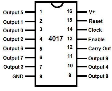
As we can see in the above picture, there are 16 pins in this IC. There are 10 output pins, which are from 1 to 7 and 9 to 11. Each of these 10 output pins are marked in an order. This is the order in which they turn high one after another. The input that comes from a timer IC will provide the timing at which the consecutive output should become high. They then continue to repeat the process after the ninth output is reached. There are six other pins excluding the output pins. These pins are used for controlling the IC directly. The six other pins for the IC will be described below.
- Pin 13
Pin 13 in the IC is an enable pin. It enables the IC to start working. The IC will work as long as the enable pin in the IC is active low. The IC switches off when the enable pin is made high. Making the enable pin high will make the IC ignore the clock input it is getting.
Related Post: Automatic LED Emergency Light Circuit
- Pin 14
Pin 14 in the IC is a clock pin. This clock is the frequency provider for the working of this IC. As we discussed above, this IC needs a clock according to whose clock cycles there is sequential high and low in the output pins. If there is no clock, it should not be left unconnected; it should be connected either to the supply voltage or to the ground, according to the input standard rules of CMOS. And one thing to note is that the clock will function on the clock highs, which means that the sequential output will change only when this pin encounters a high from the input clock.
- Pin 15
There is also a reset pin which stops the ongoing sequence of outputs and starts them over from their initial state. This reset pin is present in pin 15 of the CD4017. When the reset pin is connected to the ground, the circuit resets itself.
- Pin 8 and 16
This IC has a set of two pins for powering itself. These two pins are pin 8 and 16. The former being the ground and is connected to the negative supply voltage and the latter being the supply voltage to which the supply voltage is applied.
- Pin 12
To maintain the working of the sequential output properly, there is another pulse that is given to the IC, which completes a cycle in ten cycles of the input clock. So when the sequence of the outputs is completed and the pulse from pin 12 does not complete its cycle, then the next batch of outputs will be halted to match the frequency at which they are supposed to work. This pulse which is provided at the pin 12 is called carry out signal, hence the pin 12 is also called a carry out pin. The function it performs is called given a name. It is said if the carry over pulse ripples the IC, if it has to correct the working.
Potentiometer
A potentiometer is a three terminal passive electronic device. Potentiometer change the voltage across any component by adjusting the sliding connector across a uniform resistance material.
The potential across the potentiometer is applied through the entire length of the resistance strip, and the voltage which is obtained as the output is simply a fraction of that voltage. The maximum voltage that can be obtained from a potentiometer is simply the voltage that is applied to it.
It uses the basic voltage divider concept for working. The pin diagram of a typical potentiometer is given below.
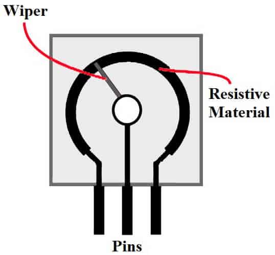
The potentiometer has two fixed terminals for input at the end of the internal resistor strip. There is a third terminal which is from connected to a slider which moves across the strip and changes the voltage between one of the input terminals and the slider terminal.
There is another device which works in the same way but is different fundamentally is a rheostat. A rheostat is also a variable resistance device but it works in a different way. It has only one fixed terminal and the connection to the circuit is from a moving slider.
Unlike the potentiometer where the two terminals that are connected to the circuit are independent of the slider position, a rheostat has one of its terminals directly connected to the circuit in consideration.
- Related Post: Christmas LED & Bulb Blinking Light String Circuit
Based on the style in which they work, potentiometers are divided into two types.
- Rotary potentiometers
- Linear potentiometers
Potentiometers are used in some applications which are listed below
- Measuring internal resistance of a battery cell
- Measuring voltage
- Used as a voltage divider
- It has been used as old school volume and tone control in televisions
- Used in wood processing machines
- Used in injection mould machines
- Related Post: 24V Flasher Circuit using 555 Timer
LED Roulette Circuit Operation & Working
The values of the resistors and capacitors are already calculated and given in the circuit. We can connect the LEDs in any order we want to, but to honour the name of the roulette game, we will try to arrange them in a circular fashion.
We use 8 LEDs in this circuit, but there is a way to use all the ten synchronized outputs from the decade counter. The eight LEDs are connected to the outputs of the decade counter CD4017. The input to the decade counter is provided by the timer IC that we used. The 555 timer IC in the circuit diagram is set to use in astable mode.
As soon as the connections are made and all the components that require powering up are powered, then the LEDs start blinking. The speed of the LEDs can be controlled using the potentiometer that we discussed above. The resistance value of the potentiometer will change the input resistance of the potentiometer, and that will in turn change the oscillation frequency of the timer IC.
In this way we can change the rate at which the clock pulse is sent to the decade counter. The new clock pulse which is fed to the decade counter affects the rate at which the outputs are made high, so that LEDs in the roulette circuit now blink at a different rate than before.
Related Electronic Projects Circuits:
- Automatic Bathroom Light Switch Circuit Diagram and Operation
- Car Speed Detector Circuit – Working and Source Code
- Smart Home Automation System – Circuit and Source Code
- IC 555 Timer Calculator with Formulas and Equations
- LED Resistor Calculator | Required Value of Resistor for LED’s Circuit Calculator
- Emergency LED Lights. Powerful & Cheap Circuit LED-716 LED Light Schematic
- Simple Touch Sensitive Switch Circuit using 555 Timer & BC547 Transistor


I Can’t read any article?
Hi James, So sorry to hear that. All the web-pages are working correctly atm, Can you please show the exact error you face while tying to open this article? We will try our best to solve the issue ASAP
I need these apps because iam an electrician I need to know more