How to Install a 15/20A Single-Pole, Two Pole and Quad Tandem Breakers for 120/240V
There are several types of circuit breakers, such as standard 120V single-pole and 240V two-pole breakers, GFCI and AFCI breakers etc. A special type of breaker is the tandem breaker, which fits into a single slot designed for a standard breaker but serves two separate 120V circuits.
Similarly, a quad (four-pole) tandem breaker fits into two adjacent slots and can serve:
- Two 240V circuits (if the handles are physically tied),
- Three circuits (one 240V and one 120V), or
- Four individual 120V circuits, depending on the breaker configuration.
Tandem breakers are available in 1-pole and quad-pole and especially useful when a service panel or load center is full and no additional full-size breaker spaces are available.
What is a Tandem Breaker?
A tandem breaker (also known as a twin, duplex, double-stuff, or slimline breaker) is a type of miniature circuit breaker that fits two independent 120V circuits into a single 1-pole breaker slot in the panel. It looks like two thin breakers combined into the space of one. It is used when you run out of space, as they add an extra circuit in a full panel, which avoids costly upgrades and installations of extra subpanels.
Tandem Breakers are single-slot devices that contains two separate circuit breakers. This feature allow them for two circuits to be installed in the space of one. They are useful for adding circuits to a crowded electrical panel. It is only applicable if the panel is designed to accept them, as not all are. A panel rated for tandem breakers will have a notch in the busbar, other indicator (such as “T” or “CTL” in the slot or panel’s manufacturer specifications.
When and Why is it Used?
Tandem breakers are used for residential circuits in older houses with limited panel space when:
- The breaker panel runs out of spaces for additional circuits.
- The panel permits tandem breakers in certain slots (as labeled by the manufacturer).
- You need to add more branch circuits without replacing or upgrading the panel.
How are Tandem Breakers Differ than the Standard Breaker?
A tandem breaker occupies a single full-size breaker slot but functions as two individual breakers, which can even have different amperages. This compact design frees up space in a panel, which is helpful when the panel is full and needs more circuits.
In other words, A standard 1-pole breaker serves one circuit. A tandem breaker has two separate trip mechanisms, and serve two circuits independently. Both circuits share the same physical slot but are electrically isolated.
Tandem breakers are designed for standard 120V circuits and are not suitable for running 240-volt circuits (except if there is a connector (handle tie) to physically join the main switch of two separate breakers) – For more info, see the wiring diagrams given below).
Good to Know:
- Not all panels allow tandem breakers. Only use them in panel slots listed as “T” (tandem) or “CTL” (Circuit Total Limiting) compatible.
- Tandem breakers are NOT the same as double-pole breakers. A double-pole breaker is used for 240V circuits and ties both poles together.
If tandem breaker is not a suitable option, or if your panel does not allow tandem breakers, you have alternation solutions such as:
- Install a subpanel, or
- Upgrade to a larger main panel, or
- Rearrange/load-balance circuits properly.
Limitation of Tandem Breakers:
- A single-pole tandem breaker connects to the same hot busbar (either Hot 1 or Hot 2). Because both of its poles land on the same phase, it cannot be used to supply 240V loads (such as kitchen countertop receptacle circuits) that require two different hot legs.
- 1-pole tandem breakers also must not be used for multi-wire branch circuits (MWBCs) that share a neutral conductor, because an MWBC requires the two hot wires to be on opposite phases with a common trip, neither of which a tandem breaker provides.
- Tandem breakers are not manufactured with built-in GFCI or AFCI protection, so they cannot directly provide those safety functions.
- Tandem breakers don’t increase the main panel amperage or subpanel overall capacity. Adding too many tandem breakers can overload the service capacity of the electrical panel.
- The electrical panel must be compatible and specifically rated to accept tandem breakers.
- Higher amperage tandem breakers may generate more heat than standard breakers in the same space, which could lead to overheat the panel.
- Using additional tandem breakers increases the total load on the panel. Therefore, you must calculate the main panel’s load capacity (to avoiding cross the limit) before adding more circuits to avoid overloading, overheating, equipment failure, and potential fire hazards.
- Due to the complexities of electrical systems, it is highly recommended to consult a professional electrician before installing tandem breakers to ensure the panel is properly rated and to prevent potential overloading.
Warning: Controlling two circuits from one slot using tandem breaker can cause confusion without proper labeling and color coding.
Can I Fit a Tandem Breaker in a Panel from a Different Manufacturer?
There are various types of load centers and main panel boxes manufactured by different companies. For example, Square D offers the QO series and the Homeline (HOM) series, while Cutler-Hammer produces the CH series and the BR series. Each panel type is designed to accept only its specific breaker model. A breaker made for one series will not fit into another, until you hit it with a hammer.
In addition, the NEC requires that all electrical equipment must be UL-listed. This applies to circuit breakers as well. Therefore, always use UL-listed breakers that are specifically approved and designed for the exact panel model you are working with.
Good to Know: NEC doesn’t outright ban tandem breakers. They are allowed if the panel is designed and listed for them. Meanwhile, NEC 408.54 requires a physical rejection feature so you can’t overload a panel with too many OCPDs.
Wiring 1-Pole Tandem Breaker for 120V
In the following wiring diagram, a 15A/20A, 120/240V single-pole tandem breaker is installed in a single slot that is normally designed for a standard 1-pole 120V breaker.
As shown in the figure, the 1-pole tandem breaker is connected to Hot 1, which means it can only be used to supply two separate 120V circuits. In this example circuit, the 15A section of the tandem breaker feeds a 15A, 125V outlet (NEMA 5-15), while the 20A section supplies a 20A, 125V outlet (NEMA 5-20).
Click image or open in a new tab to enlarge
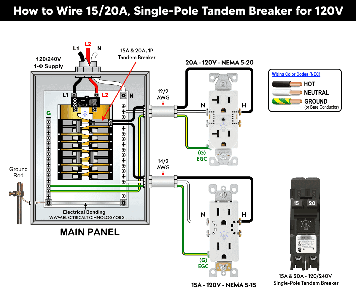
This arrangement of one single-pole tandem breaker can be used for:
- Two individual 120V circuits
Good to Know: A single-pole tandem breaker cannot be used for a 240V circuit unless the two breaker poles are installed side by side in the main panel and their handles are physically tied together with a handle-tie. This is required because both hot conductors (Hot 1 and Hot 2) must disconnect simultaneously if a fault occurs on either conductor. Without a handle-tie, only one breaker may trip while the other remains energized, which poses a serious shock hazard.
Warning: It is against code to use two single-pole breakers or a single-pole tandem breaker to supply 240V unless both breakers have the same ampere rating, connected to both Hots (Hot 1 and Hot2) and their main switches are mechanically interconnected.
Wiring Two 1-P Tandem Breakers for 240V & 120V
As mentioned earlier, you cannot use a single-pole tandem breaker alone for 240V circuits. To obtain 240V using single-pole tandem breakers, both tandem breakers must be installed side by side in a 120/240V main panel so that each one connects to a different hot bus (Hot 1 and Hot 2).
In addition, when the breaker ratings are different (e.g., 15A/20A/20A/15A), you must use either both inside terminals or both outside terminals to form the 240V circuit, not the 1st and 3rd terminals or the 2nd and 4th terminals.
If all terminals are the same rating (e.g., 20A/20A/20A/20A), you may use any one terminal from the first breaker and any one terminal from the second breaker, as long as each terminal comes from a different breaker.
This is required because each breaker is fed from a different hot bus (Hot 1 and Hot 2). If you accidentally select two terminals from the same breaker, the load will still be supplied from the same 120V hot leg, resulting in 120V instead of 240V.
To meet NEC requirements, you must use a handle tie that physically links the switches of both breakers. Depending on the breaker brand, use BHT, CH, CHHT, or TOW handle ties. This ensures that if one breaker trips, the second breaker must also trip, disconnecting both hot conductors (Hot 1 and Hot 2) simultaneously to eliminate shock hazards.
In the following diagram, two 20A, 240V single-pole tandem breakers are installed side by side. The inside terminals are used to supply a 20A, 240V outlet (NEMA 6-20), while the lower 20A terminal is used for a 20A, 120V outlet (NEMA 5-20).
The upper 20A terminal is unused and may be utilized later for an additional 120V circuit.
Click image or open in a new tab to enlarge
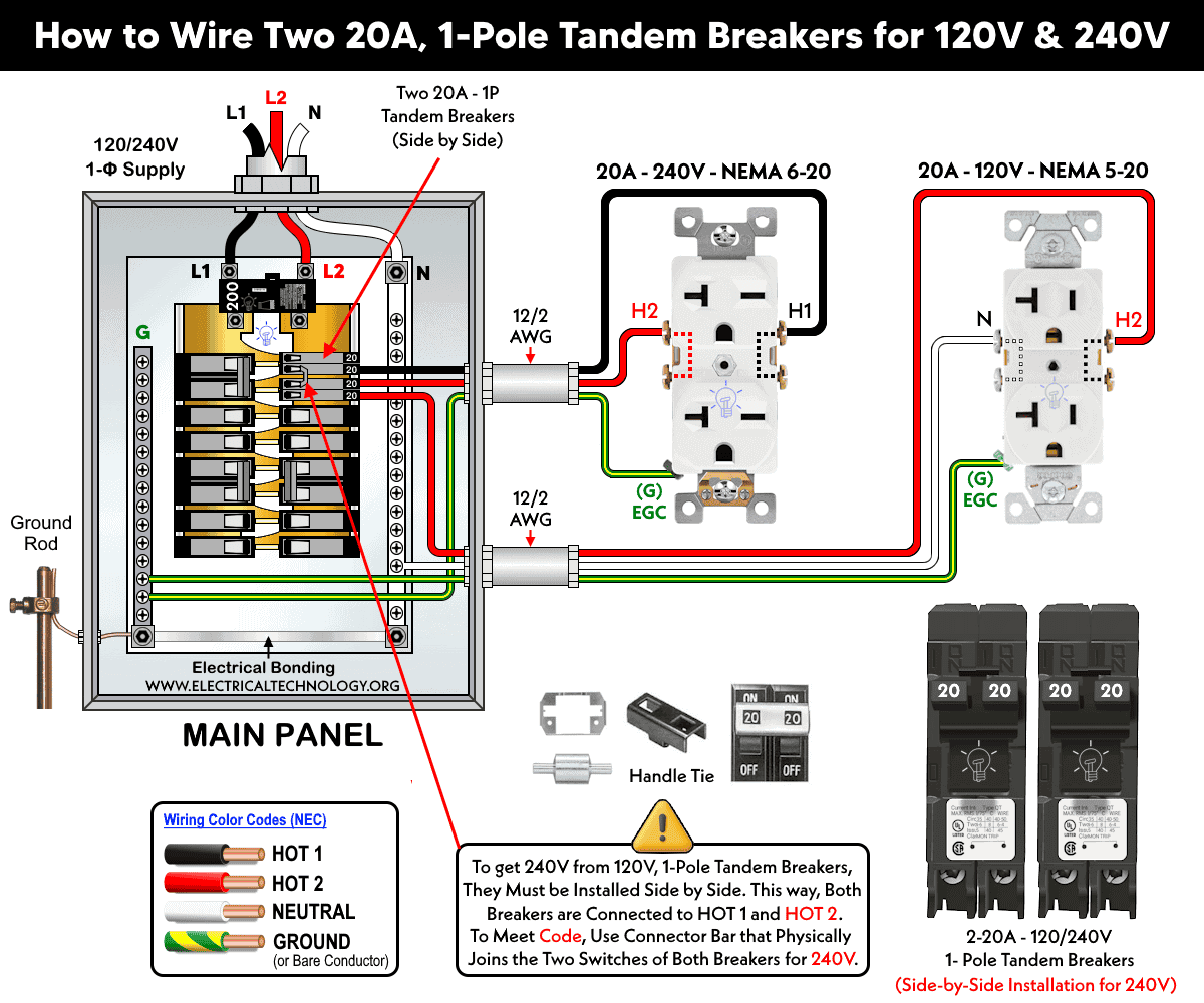
This arrangement of two single-pole tandem breakers can be used for:
- Four individual 120V circuits
- Two 240V circuits
- One 240V circuit and two 120V circuit
Wiring Quad Tandem Breakers for 120V & 240V
The following wiring arrangement serves the same purpose as the configuration shown above. In simple terms, a quad tandem breaker is essentially four single-pole breakers combined into one compact unit.
In the wiring diagram below, we have used a quad tandem breaker consisting of two 15A single-pole breakers and one 20A two-pole (120/240V) breaker to supply both 120V and 240V outlets. As shown, the 20A inside terminals are used to feed a 20A, 240V (NEMA 6-20) receptacle. A handle tie is installed between the switches of the inside terminals to provide a common trip mechanism in case of a fault.
The upper 15A terminal is used to supply a 15A, 120V outlet (NEMA 5-15), while the lower 15A terminal is connected to a 20A, 120V outlet (NEMA 5-20).
Click image or open in a new tab to enlarge
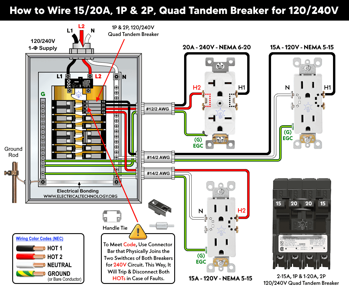
A quad breaker can also be used to supply two independent 240V circuits when equipped with a THOW (or CHHT) listed handle tie. This ensures that only the paired breakers will trip together during a fault, while the remaining breakers will continue operating and supplying power to their circuits.
This arrangement of quad tandem breakers can be used for:
- Four individual 120V circuits
- Two separate 240V circuits
- One 240V circuit and two 120V circuits
Always use a properly connected double-pole breaker for all 240V circuits. It is not code-compliant to use two separate single-pole breakers to supply a 240V load unless both breakers have the same ampere rating and their switches are mechanically linked with an approved handle tie so they operate together.
Good to Know: For 15A and 20A current ratings used in this wiring diagrams, use #14/2 cable for a 15A circuit and #12/2 cable for a 20A circuit. If the ampere rating differs, refer to NEC Table 310.16 to select the appropriate wire size.
Warning:
- Make sure to disconnect the power supply by switching OFF the breaker in the main panel before doing any electrical work.
- Never ever touch the main lugs or terminal screw used prior the main breaker. They are always energized even the main breaker is OFF.
- If you are unsure, contact a licensed electrician to do it according to the local area codes.
- The author will not be liable for any losses, injuries, or damages from the display or use of this information or if you try any circuit in wrong format. So please! Be careful because electricity is too dangerous.
Resources:
Standard Breakers & GFCI Breakers Wiring Installations
- How to Wire a 1-Pole GFCI
- How to Wire a 2-Pole GFCI
- How to Wire a 3-Phase, 3-Pole GFCI
- How to Wire a 1-Pole Breaker
- How to Wire a 2-Pole Breaker
- How to Wire a 3-Pole Breaker
- How to Wire a Tandem Breaker … You are Here
- How to Wire GFCI Circuit Breakers
- How to Wire an AFCI Breaker
Sizing Breakers, Wires, and Panels
- How to Size a Circuit Breaker?
- How to Size a Breaker and Wires in AWG with EGC for Load?
- How to Find the Proper Size of Wire & Cable In Metric & Imperial Systems
- How to Size a Load Center, Panelboards and Distribution Board?
- How to Determine the Right Size Capacity of a Subpanel?
- How to Find the Right Wire Size for 100A Service 120V/240V Panel?
- How to Size Service-Entrance Conductors and Feeder Cables?
- How to Size Feeder Conductors with Overcurrent Protection
- How to Size a Branch Circuit Conductors with Protection?
- How to Size Equipment Grounding Conductor (EGC)?
- How to Size Grounding Electrode Conductor (GEC)?
- How to Size Motors FLC, HP, Voltage, Breaker Size and Wire Size
- What is the Correct Wire Size for 100A Breaker and Load?
- What is the Right Wire Size for 15A Breaker and Outlet?
- What is the Suitable Wire Size for 20A Breaker and Outlet?
General Outlets and GFCI/AFCI Receptacles Wiring
- How to Wire an Outlet Receptacle? Socket Outlet Wiring Diagrams
- How to wire a GFCI Outlet?
- How to Wire GFCI Combo Switch and Outlet
- How to Wire an AFCI Combo Switch
- How to Wire an AFCI Outlet?
- How to a Wire 3-Way Combination Switch and Grounded Outlet?
- How to Wire Combo Switch and Outlet? – Switch/Outlet Combo Wiring Diagrams
- How to Wire a 15A – 120V Outlet – NEMA 5-15 Receptacle
- How to Wire a 20A – 120V Outlet – NEMA 5-20 Receptacle
- How to Wire a 15A – 240V Outlet – NEMA 6-15 Receptacle
- How to Wire a 20A – 240V Outlet – NEMA 6-20 Receptacle
- How to Wire a 50A – 125/250V Outlet – NEMA 14-50 Receptacle
Switches Wiring
- How to Wire Single Pole, Single Throw (SPST) as 2-Way Switch?
- How to Wire Single Pole, Double Throw (SPDT) as 3-Way Switch?
- How to Wire Double Pole, Single Throw Switch? Wiring DPST
- How to Wire Double Pole, Double Throw Switch? Wiring DPDT
- How to Wire Double Switch? 2-Gang, 1-Way Switch – IEC & NEC
- How to Wire 4-Way Switch (NEC) or Intermediate Switch as 3-Way (IEC)?
- How to Wire Auto & Manual Changeover & Transfer Switch – (1 & 3 Phase)
Finding the Number of Breakers/Outlets in a Circuit
- How to Determine the Number of Circuit Breakers in a Panelboard?
- How to Find the Number of Outlets on a Single Circuit Breaker?
- How to Find Voltage & Ampere Rating of Switch, Plug, Outlet & Receptacle
- How to Calculate the Number of Fluorescent Lamps in a Final Sub Circuit?
- How to Calculate the Number of Incandescent Lamps in a Final Sub Circuit?
- How to Determine the Number of Lighting Branch Circuits?
- How to Determine the Number of Branch Circuits? – 3 Ways
- How to Find the Number of Lights on a Single Circuit Breaker?
Main Panels Wiring Tutorials
- How to Wire 120V/240V Main Panel? Breaker Box Installation
- How to Wire 208V/120V, 1-Phase & 3-Phase Main Panel?
- How to Wire 240V, 208V & 120V, 1 & 3-Phase, High Leg Delta Main Panel?
- How to Wire 277V/480V, 1-Phase & 3-Phase Main Service Panel?
- How to Wire a Subpanel? Main Lug Installation for 120V/240V
- Single Phase Electrical Wiring Installation in Home according to NEC & IEC
- Three Phase Electrical Wiring Installation in Home – NEC & IEC
- How To Wire a Single Phase kWh Meter – 120V/240V
- How to Wire a Three-Phase Meter? 120/208/240/277/347/480/600V
General Wiring Installation Tutorials:
- How to Toggle Electric Water Heater Between 120V and 240V?
- How to Wire 120V Water Heater Thermostat – Non-Simultaneous?
- How to Wire 240V Water Heater Thermostat – Non-Continuous?
- How to Wire 3-Phase Simultaneous Water Heater Thermostat?
- How to Wire Twin Timer for 120V/240V Circuits – ON/OFF Delay
- How to Wire ST01 Timer with Relay & Contactor for 120V/240V Motors?
- How to Wire Multifunction ON/OFF Delay Timer for 120V/240V Motors?
- Even More Residential Wiring Installation Tutorials
Related Posts:
- Difference Between 1-Pole and 2-Pole Breakers – NEC & IEC
- Should GFCI Protection Be in the Main Panel or Receptacle?
- Can you use 15A Breaker on 20A Circuit and Vice Versa?
- Can I Use a 1-Phase Breaker on a 3-Phase Supply & Vice Versa?
- Can I Use a 240V Breaker on a 120V Circuit and Vice Versa?
- Can You use a 15A Outlet on a 20A Circuit and Vice Versa?
- How Does a Standard Breaker Respond to Electrical Fault?
- Why Doesn’t a Standard Breaker Protract Against Ground Faults?
- How Do GFCI and Standard Breakers Respond to Ground Faults?
-
 How to Install a Wireless Smart Scene Switch
-
 How to Wire Smart Scene Controller Switch
-
 How to Install a Home and Away Wireless Smart Switch
-
 Arkansas School Uses Rooftop Solar to Raise Teacher Pay
-
 How to Install a Wire-Free Smart Dimmer Anywhere Companion
-
 How to Wire a Smart Wireless Switch and Anywhere Companion