How to Make a Simple LED Flashing Circuit using 555 Timer IC
LED Flashing / Blinking Circuit using 555 Timer IC
While getting started with electronics, you must be thinking about making useful and simple circuits that you can get embarked one and costs you less. Here is one for you- Flash Lamp Using 555 Timer IC. Using cost-effective electronic components, circuit diagram, pin diagram, this article will guide you step by step to make a flash lamp using 555 Timer IC. Before starting with the designing process, let me give you some brief idea about the flash lamp and the 555 timer IC used in the circuit.
- Related Project: Traffic Light Control Electronic Project using IC 4017 & 555 Timer
What is Flash Lamp?
A portable source of light is which incandescent light source (light bulb) or light emitting diode (LED) is used. In this project, we are using LED (light emitting diode) due to its energy efficient and long lasting features as a source of light.

Components Required For LED Circuit
- 555 timer IC
- 9V Battery
- Resistor – 1K ohm X 2 and 470k ohm
- Capacitor – 1μf
- Jump wires
- Battery clip
- L.E.D
- Breadboard
Related Project: Clap Switch Circuit Electronic Project Using 555 Timer
Steps to Make a Simple LED Flashing Circuit
Collect all the required components and get ready to put all the components together!
Step 1:- Put the 555 timer IC on breadboard.
Step 2:- Connect pin 1 of 555 Timer IC to the ground as shown below. You can see the pin structure of 555 Timer IC in the pin diagram shown above.
Step 3:- Connect the positive end of the capacitor with pin 2 of 555 Timer IC. Longer lead of a polarized capacitor is the positive and the shorter one is negative end
Step 4:- Join the negative lead of the capacitor with the ground of battery.
Step 5:- Connect pin 6 of timer IC with pin 2.
Step 6:- Connect the pin 3 with the positive lead of LED using 1kΩ resistor.
Step 7:- Connect the negative lead of LED with ground
Step 8:- Connect pin 4 with the positive end of the battery.
Step 9:- Leave Pin 5 and don’t connect it with anything.
Step 10:- Connect pin 7 with pin 6 using a 470kΩ resistor.
Step 11:- Connect pin 7 with the positive end of battery using the 1kΩ resistor.
Step 12:- Connect pin 8 with the positive end of the battery.
Step 13:- To start the power supply in circuit, connect the battery leads with breadboard.
- Related Project: PCB Design of LED Flasher Circuit. Step by Step
Working of Blinking LED Light Circuit
Once you connect the battery to circuit, the LED should flash. Make sure the battery is connected to breadboard and power is reaching to components of circuit.
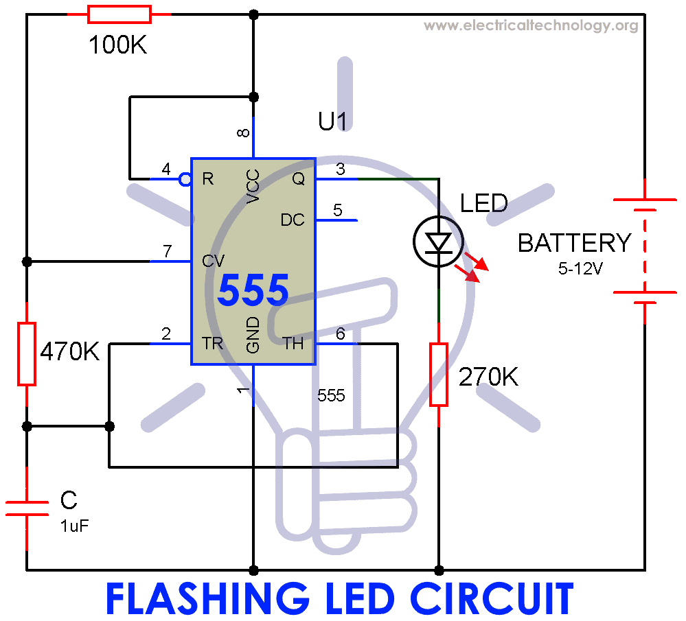
Circuit Diagram of Flash Lamp Using 555 Timer IC
Here, the circuit consists of an A-stable multi vibrator using 555 Timer IC which creates a square wave. The circuit has an on-state time of 0.94 Seconds and OFF time of 0.47 Seconds.
To Rate of flashing lamp can be calculated as
Ton = 0.69*(R1 + R2)*C | Toff = 0.69*R2*C
T total = Ton + Toff = 0.69*(R1 + 2*R2)*C
Due to the internal circuitry of 555 Timer IC, the output keeps switching between sinking to sourcing.
Related Post: LED String/Strip Circuit Diagram Using PCR-406
Note-
- If you want to add more LEDs, connect them parallel with first LED using proper resistors.
- You can also use a decade counter (IC 4017) to connect more LEDs.
- To easily tune the rate of flash, either one of the resistance can be replaced with a potentiometer.
- Make sure that all the connection are tightly fixed and are connected with each other.
Related Project: How to Make an LED Project with ATMega Microcontroller?
Bottom Line
In this article we have tried to provide you the simplest and effective way to design a flash lamp using 555 Timer IC along with the basic knowledge of 555 Timer and its internal circuitry with the help of block diagram ,Wave form and pin diagram. Hope, you will be able to successfully design a flash Lamp using 555 timer IC with our step by step process in this article.
Related Projects:


You will never get the LED to illuminate with 270k