Carrier Acquisition, Need for Carrier Acquisition & Techniques
What is Carrier Acquisition? The Need For Carrier Acquisition & Its Techniques
What is Carrier Acquisition?
In suppressed carrier communication, the demodulation process requires an identical local carrier at the demodulator. This local carrier needs to have same frequency and phase as the transmitted signal. which is acquired using carrier acquisition.
The process of acquiring or extracting carrier frequency from the received signal is called carrier acquisition.
Why We Need Carrier Acquisition?
Amplitude Modulated Suppressed Carrier signal needs a locally generated signal having the same phase and frequency as the received signal (carrier signal).
If the frequency or phase of the signal is different than the received signal, then the demodulated message signal we get will be distorted or may be completely destroyed. To avoid such problems and get a clear message signal, we need an identical carrier.
Suppose we receive a DSB-SC signal which is m(t)cos(ωct + ϴi) and the carrier generated by demodulator has a frequency (ωc+Δω) and phase ϴo i.e. the local carrier is 2cos((ωc+Δω)t+ϴo).
Thus the demodulated signal e(t) will be:
e(t) = m(t) cos(ωct + ϴi) 2cos((ωc+Δω)t+ ϴo)
e(t) = 2m(t) cos(ωct + ϴi) cos((ωc+Δω)t+ ϴo)
e(t) = m(t) [cos {(ωc+ωc+Δω) t +ϴi+ϴo} + cos(Δωt+ ϴi-ϴo)]
e(t) = m(t) cos {(ωc+ωc+Δω) t +ϴi+ϴo} + m(t)cos(Δωt+ ϴi-ϴo)
By passing through Low-pass filter
e(t) = m(t)cos(Δωt+ ϴi-ϴo)
If the frequency difference Δω = 0 and phase difference (ϴi-ϴo) = 0. Then
e(t) = m(t)
Which means the message signal is successfully received.
However, if the frequency difference Δω = 0 and phase difference (ϴi-ϴo) ≠0. Then
e(t) = m(t)cos(ϴi-ϴo)
This means that the message signal is attenuated by factor cos(ϴi-ϴo). if (ϴi-ϴo)= π/2 , then e(t) = 0 and the message signal is completely destroyed.
Another case is if the phase difference (ϴi-ϴo) =0 and frequency difference Δω ≠ 0. Then
e(t) = m(t)cos(Δωt)
This equation implies that the same message signal is multiplied with a sinusoid of frequency Δω. Δω is usually very small. which means that the message signal will go from maximum to zero at the rate of two times its frequency. This is called beating effect. This beating effect distorts the original signal even if the Δω is very small.
- Related Post: Quantization & Sampling? Types & Laws of Compression
Techniques Of Carrier Acquisition
There are few different techniques used for carrier acquisition. Some of them are given below.
Phase-Locked Loop (PLL)
Phase locked loop, commonly known as PLL is one of the most widely used circuit for carrier acquisition. It tracks the phase and frequency of the incoming/reference signal and generates a stable frequency signal.
A PLL is made up of 3 components
- VCO
- Phase detector
- Loop filter
VCO
VCO stands for the voltage controlled oscillator. It generates frequency signal, which is controlled by an external voltage signal. The frequency signal produced by VCO is
ω(t) = ωc + ceo(t)
ωc is free running frequency when external voltage eo(t) is zero. C is constant of VCO & eo(t) is the external voltage signal. The frequency is increased or decreased according to this voltage signal eo(t).
Phase Detector
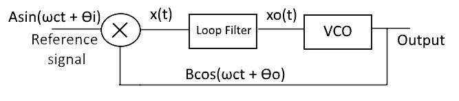
A Multiplier is used as a phase detector. It has 2 input signals, a reference signal & the output of VCO.
It generates a signal proportional to the phase difference between the two signals.
Suppose the input signal is Asin(ωct + ϴi) & output is Bcos(ωct + ϴo),then its product is
e(t) = Asin(ωct + ϴi) Bcos(ωct + ϴo)
e(t) = AB/2 sin(2ωct + ϴi + ϴo) + AB/2 sin(ϴi – ϴo)
The high-frequency term is filtered the loop filter discussed below.
Loop Filter
This loop filter is actually a narrow band low pass filter. It blocks any high-frequency components from its input signal (output of multiplier) and generates a dc voltage. which is supplied as input to the VCO.
The signal after passing through loop filter becomes
eo(t) = AB/2 sin(ϴi – ϴo)
If the phase difference (ϴi – ϴo) is not zero then the signal eo(t) will generate DC voltage & supplies to the VCO. This voltage leads to increment in the VCO frequency.
The process is repeated until the frequency & phase matches the input signal. Such case is called in phase lock or phase coherent state.
Carrier Acquisition In DSB-SC
In DSB-SC scheme the level carrier can be regenerated using two methods discussed below.
Signal Squaring Method:
This method is used for carrier acquisition in DSB-SC communication.
The block diagram of signal-squarer is given below.
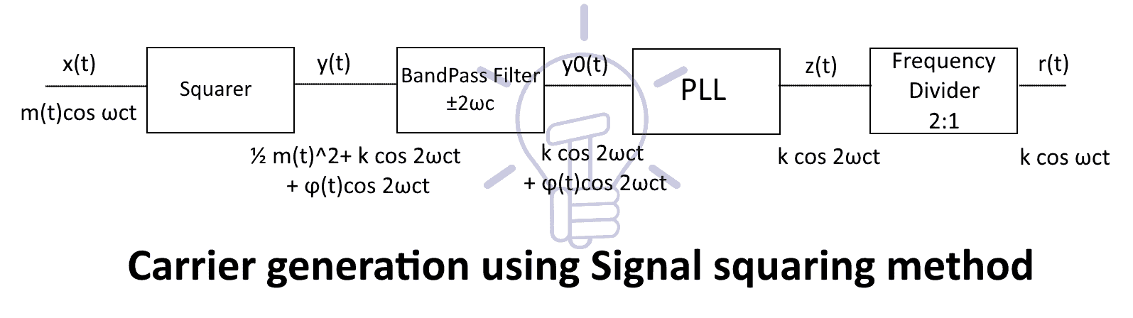
The received DSB-SC signal x(t) is first passed through a squarer, which takes the square of the signal.
The received signal x(t) is:
x(t) = m(t)cos ωct
The output y(t) of squarer is:
y(t) = x2(t)
y(t) = (m(t)cos ωct)2
y(t) = m2(t)cos2 ωct
y(t) = ½ m2(t)(1+cos 2ωct)
y(t) = ½ m2(t)+ ½ m2(t)cos 2ωct
As we can see, m2(t) is a non-negative signal i.e. it is positive for every value of t. Therefore, it has positive average (DC) value.
Let suppose the average value of m2(t)/2 is k then
½ m2(t) = k + ϕ(t)
Now the signal y(t) can be expressed as:
y(t) = ½ m2(t)+ (k + ϕ(t))cos 2ωct
y(t) = ½ m2(t)+ k cos 2ωct + ϕ(t)cos 2ωct
After passing through the narrow-band band-pass filter, it will block m2(t) completely because of its ω=0. k cos 2ωct will flow through. However, some parts of ϕ(t)cos 2ωct will also flow out because it has almost no power at 2ωc. Thus the signal y0(t) becomes:
y0(t) = k cos 2ωct + ϕ(t)cos 2ωct
The next stage is PLL. The PLL will block any residual frequencies & produce a stable frequency signal z(t), which is :
z(t) = k cos 2ωct
The last stage of signal squarer is the divider. The divider divides the frequency of the input signal by two. Thus the output signal becomes a pure sinusoidal wave of frequency ωc.
The output r(t) of signal squarer is:
r(t) = k cos ωct
COSTAS Loop
John P.Costas was an Electrical engineer. In 1950, he invented the method to use a modified PLL to regenerate the carrier signal in suppressed carrier communication. This circuit is known as Costas loop.
Costas loop is used to acquire the carrier signal in DSB-SC communication.
Block Diagram
The block diagram of Costas loop is given below:

This diagram shows the received signal DSB-SC signal m(t)cos(ωct+ϴi) is multiplied with local carriers cos(ωct+ϴo) & sin(ωct+ϴo) separately to get x1(t) and x2(t) respectively.
The VCO generates the local carrier cos(ωct+ϴo), which is phase shifted by –π/2 to generate sin(ωct+ϴo).
The signal x1(t) and x2(t) is given by:
x1(t) = m(t)cos(ωct+ϴi) cos(ωct+ϴo)
x1(t) = ½ m(t){cos(ϴi– ϴo) +cos(2ωct+ ϴi +ϴo)}
x1(t) = ½ m(t)cos(ϴi– ϴo) +½ m(t)cos(2ωct+ ϴi +ϴo)
x2(t) = m(t)cos(ωct+ϴi) sin(ωct+ϴo)
x2(t) = ½ m(t){sin(ϴi– ϴo) +sin(2ωct+ ϴi +ϴo)}
x2(t) = ½ m(t)sin(ϴi– ϴo) +½ m(t)sin(2ωct+ ϴi +ϴo)
The signal x1(t) & x2(t) is then passed through low pass filter, it blocks high frequency components & allow low frequency components. Thus producing y1(t) & y2(t) for the signal x1(t) & x2(t) respectively.
y1(t) = ½ m(t)cos(ϴi– ϴo)
y2(t) = ½ m(t)sin(ϴi– ϴo)
These two signals y1(t) & y2(t) are then multiplied to produce z(t) as:
z(t) = ½ m(t)cos(ϴi– ϴo) ½ m(t)sin(ϴi– ϴo)
z(t) = ⅛ m2(t){sin(0) + sin2(ϴi– ϴo)}
z(t) = ⅛ m2(t) sin2(ϴi– ϴo)
Thus the signal z(t) will produce a DC voltage depending on the phase difference (ϴi– ϴo).
If there is any phase difference then this signal will produce DC voltage.
The narrowband low-pass filter will suppress any frequency components and produce a pure DC signal. This DC signal will either increase or decrease the frequency of the VCO.
When the frequency and phase of the input signal and matches the VCO output, then the phase difference (ϴi– ϴo) = 0 and the DC output of Narrowband LPF becomes 0. In such case, the VCO output remains unchanged.
The output of the VCO is the acquired carrier we need & the signal y1(t) is the demodulated message signal.
y1(t) = ½ m(t)cos(ϴi– ϴo)
y1(t) = ½ m(t)cos(0)
y1(t) = ½ m(t)
Carrier Acquisition In SSB
In single sideband (SSB) communication, the methods of carrier acquisition do not work as it did in the DSB-SC. The signal-squaring method & Costas loop does not work. The reason is that after squaring SSB signal, the product terms does not contain a pure sinusoid of the carrier frequency as in DSB-SC. So extracting the carrier through such method does not work.
However, if we transmit a carrier signal of low power with SSB signal, it can be extracted using a narrowband band-pass filter. The said signal is then amplified, in such way the demodulator will know the frequency & phase of the carrier signal.
Vestigial Sideband (VSB) has the same situation as SSB and it also needs a separate carrier with the transmitted signal.