Digital to Analog Converter (DAC) – Types, Working & Applications
Digital to Analog Converter (DAC) – Types, Working, Block Diagram & Applications
Signals are mainly classified into two types i.e. Analog & Digital signal. The data or information that we perceive in real world exists in analog form while the digital devices such as cellphone, calculator & computer can only understand a data signal in digital domain. Analog to Digital (ADC) & Digital to analog converter (DAC) are the two types of converters that we use in our daily life to convert the signals into each other.
What is DAC (Digital to Analog Converter)?
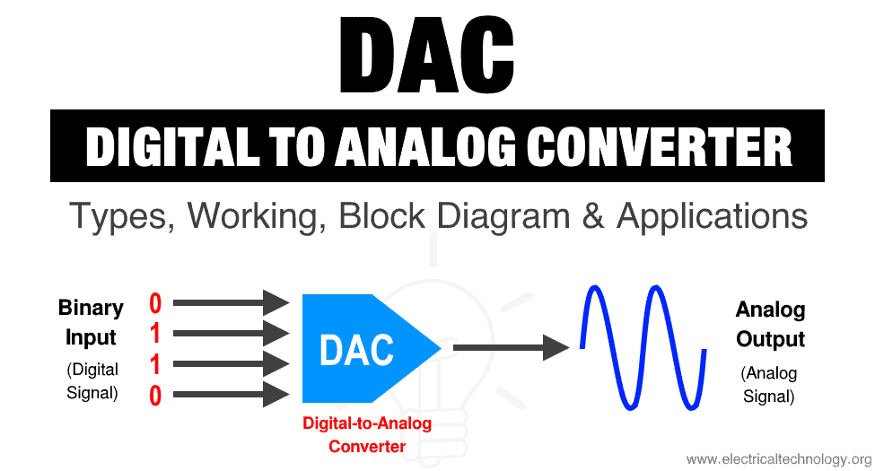
Digital to analog converter is an electronic circuit that converts any digital signal (such as binary signal) into an analog signal (voltage or current).
The digital signal such as the binary signal exist in the form of bits & it is the combination of 1’s & 0’s (or High & low voltage levels). The DAC converts these bits into an analog voltage or current.
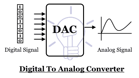
The DAC has several digital inputs & a single analog output.
Need of DAC
The information exist in real world is in analog form. Why we convert them into digital form in the first place if we want to convert them back? The processing speed of a digital computer is very fast & can compute or process any data in a matter of micro seconds. It conserves time & helps in processing complex data according to our need. But we cannot understand the digital data in real world.
In order to understand the data that we process in a digital domain, we need to convert it into analog domain. An example of that would be the process of audio & video editing. We capture the data using our digital camera & microphone to convert the analog data into digital. We process it using our computers to edit it according to over needs. In order to view our edited work, we use DACs to convert it back into the analog domain to view & listen it through our screen & speakers.
Related Posts:
- Binary Multiplier – Types & Binary Multiplication Calculator
- Binary Adder & Subtractor – Construction, Types & Applications
Working of DAC
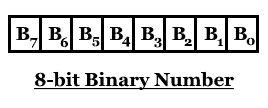
The digital binary data exists in the form of bits. Each bit is either 1 or 0 & they represent its weight corresponding to its position. The weight is 2n where the n is the position of the bit from right hand side & it start from 0.
Bit Weight = 2n
Bit weight of 4th bit from left= 2n = 23 = 8
The bit weight is multiplied by the bit value. Since the bit could be either 0 or 1, it means;
Bit value of 1 x bit weight = 1 x 2n = 2n
Bit value of 0 x bit weight = 0 x 2(n-1) = 0
Now adding the weights of all the bits with its value in a binary number 10011;
1 00112 = (1 x 24) + (0 x 23) + (0 x 22) + (1 x 21) + (1 x 20)
100112 = 16 + 0 + 0 + 2 + 1
100112 = 19
This is how the digital to analog converter DAC works by adding the weights of all corresponding bits with its value to generate the analog value at its output.
Related Posts:
- MUX – Digital Multiplexer | Types, Construction & Applications
- DEMUX – Demultiplexer | Types, Construction & Applications
Types of DAC
The DAC can be designed using one of the following types of circuits.
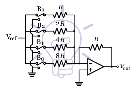
Weighted Resistor Method
The weighted resistor method utilizes the summing operational amplifier circuit. The summing amplifier adds the input signals with different gains corresponding to their resistors.

Vout = – {(Rf /R0) V0 + (Rf /R1) V1 + (Rf /R2) V2 +… + (Rf/Rn-1) Vn-1}
It can be used as a DAC if we assign each resistor a with specific value to scale their gain in the form of 2, 4, 8 ,16 & so on. As we know the Vref (the reference voltage or the maximum analog output voltage) is the only input signal (beside the binary input) so;
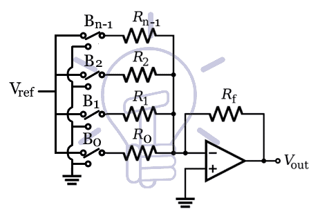
Vout = – {(Rf /R0) Vref + (Rf /R1) Vref + (Rf /R2) Vref +… + (Rf/Rn-1) Vref}
Vout = – Vref {(Rf /R0) + (Rf /R1) + (Rf /R2) +… + (Rf/Rn-1) }
In this circuit, the binary input 1 or 0 is used for switching between the vref & GND. The input B = 1 means the switch is connected with Vref & B = 0 means the switch is connected with GND. In such case the equation for a binary number B0, B1, B2… Bn ; where B0 is LSB & Bn is MSB, become
Vout = – Vref { B0 (Rf /R0) + B1 (Rf /R1)+ B2 (Rf /R2) +… + Bn-1 (Rf/Rn-1) }
The resistor Rf = R. while the R0, R1, R2, & Rn-1 are scaled to provide the necessary gain corresponding to the weight of each bit. The resistors are scaled with the values 2(N-1)-n, such that;
Rn = 2(N-1)-n R where N is number of bits & n is the bit position
So
Vout = – Vref { B0 (R/2(N-1) R) + B1 (R /2(N-2) R) + B2 (R /2(N-3) R) +… + BN-2 (R /21 R) +BN-1 (R /20 R) }
Vout = – Vref { B0 (1/2(N-1)) + B1 (1 /2(N-2)) + B2 (1/2(N-3)) +… + BN-2 (1 /2(1)) +BN-1 (1 /20) }
The output voltage for a 4 bit binary number would be;
Vout = – Vref { B0 (1/23) + B1 (1 /2(2)) + B2 (1/2(1)) + B3 (1/20) }
Vout = – Vref { B0 (1/8) + B1 (1 /4) + B2 (1/2) + B3 }
As you can see, each resistor is scaled to add the bit-weight of each bit of a binary input.
Simplified formulae for such circuit would be
Vout = – Vref { B0 (1/2(N-1))) + B1 (1 /2(N-2)) + B2 (1/2(N-3))) + B3 (1/2(N-4)) + B4 (1/2(N-5) +…}
Where the denominator 2(N-1) represents the scaling factor of each corresponding resistor.
Related Posts:
- PNP Transistor? Construction, Working & Applications
- NPN Transistor? Construction, Working & Applications
Example:
Let’s convert a binary number of 01101 into an analog output where the vref = 10v.
So the N = 5
Vout = – Vref { B0 (1/2(N-1))) + B1 (1 /2(N-2)) + B2 (1/2(N-3))) + B3 (1/2(N-4)) + B4 (1/2(N-5) }
Vout = – Vref { B0 (1/24) + B1 (1 /23) + B2 (1/22) + B3 (1/21) + B4 (1/20) }
Vout = – (10) { 1 (1/25) + 0 (1 /24) + 1 (1/23) + 1 (1/22) + 0 (1/21)}
Vout = – (10) { 1/25 + 0 + 1/23 + 1/22 + 0}
Vout = – (10) { 1/32 + 1/8 + 1/4}
Vout = – 4.0625v
Drawbacks of Weighted Resistor Method;
- Increasing the number of input bits require large value resistors (increases exponentially)
- The values of large resistors are not accurate & always have some % of give or take.
- The error in resistor value causes to lose the accuracy of the DAC for large binary numbers.
- Due to the difficulty of designing resistors, it is not practical to implement it.
Related Post:
These drawbacks can be resolved by using the other method discussed below.
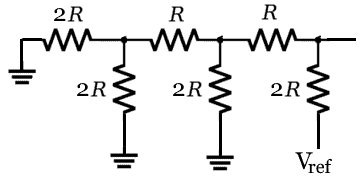
R-2R Ladder Circuit
This method is more precise, accurate & easy to design then the weighted resistor method. R- 2R ladder circuit is made by adding combination R & 2R resistor in cascaded form as shown in the following figure.
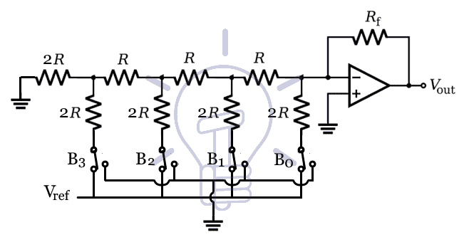
There are only two types of resistors used. Each stage contains R & 2R, is used for a single bit. There is switch between the Vref & GND which is controlled by the binary input. Bit 0 means the GND is connected & bit 1 means the Vref is connected.
Working;
Let’s assume a 3 bit DAC using R-2R ladder network.
B2B1B0 are the 3 bits of the binary input. When B0 = 1, B1 & B2 = 0. Then the equivalent circuit would be;

Replacing the 1st stage with its Vth & Rth;
Vth = Vref/2 & Rth = R
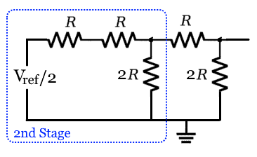
Now the 2nd stage Vth & Rth;
Vth = Vref/4 & Rth = R
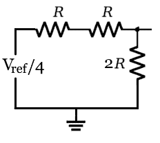
Now the 3rd stage Vth & Rth
Vth = Vref/8 & Rth = R
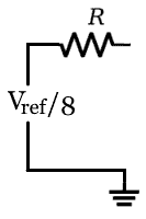
So the output voltage in this case would become
Vout = -Vth (Rf/R) = -(Vref/8) (R/R) = -(Vref/8)
When B1 = 1, B0 & B2 = 0. Then the equivalent circuit would be;

Applying the same process the output voltage will be
Vout = -(Vref/4)

When B2 = 1, B0 & B1 = 0. Then the equivalent circuit would be;
Applying the same process the output voltage will be
Vout = -(Vref/2)

As we know the output of the opamp is the sum of individual inputs where each bit is
Vout = -{ B0 (Vref/8) + B1 (Vref/4) + B2 (Vref/2)}
Vout = – Vref { B0(1/8) + B1 (1/4) + B2 (1/2)}
Vout = – Vref { B0(1/23) + B1 (1/22) + B2 (1/21)}
We can generalize this formula for an N bit binary number as;
Vout = – Vref {B0(1/2N) + B1(1/2N-1) + B2(1/2N-2) +…+ BN-2(1/22) + BN-1(1/21)}
Related Posts:
- Different Types of Sensors with Applications
- Types of Digital Logic Gates – Boolean Logic Truth Tables & Applications
Example:
Convert a binary number of 10110 into an analog output where the vref = 12v
The number of bit N = 5
Vout = – Vref {B0(1/2N) + B1(1/2N-1) + B2(1/2N-2) +…+ BN-2(1/22) + BN-1(1/21)}
Vout = – Vref {B0(1/25) + B1(1/24) + B2(1/23) + B3(1/22) + B4(1/21)}
Vout = – (12) {(0)(1/25) + (1)(1/24) + (1)(1/23) + (0)(1/22) + (1)(1/21)}
Vout = – (12) {(1/24) + (1/23) + (1/21)}
Vout = – (12) {(1/16) + (1/8) + (1/2)}
Vout = – 8.25 v
Advantages of R-2R Ladder DAC;
- Uses only two types of resistors
- Easiliy scalable to any number of bits
- Output impedance is always R
PWM Based Conversion
It is another method used in digital to analog converter & microcontrollers such as Arduino can be easily programed to utilize its PWM function to generate an analog output.
Pulse Width Modulation or PWM is a method of varying the average power of a signal by varying its duty cycle. He duty is the % turn on time of the signal, the % amount of time for which the signal remains high. Like 40% duty cycle signal means it stays high for 40% of time & stays low for 60%.
We can use a binary number to generate such type signal whose duty cycle depends on the binary digit. The PWM wave is the filtered using a low pass filter to remove the fluctuations & provide a smooth analog voltage.
The low pass filter used can be a first order. 2nd order low pass filter would be a great choice for a PWM base digital to analog converter.
- Related Post: Sum Of Product (SOP) & Product Of Sum (POS)
Resolution & Step Size of Digital to Analog Converter
Resolution & step size of a DAC plays important role in the precision & accuracy of the analog output.
Resolution of DAC
Resolution is the number of possible output levels a DAC can produce. It depends on the number of input bits.
Resolution = 2n
The resolution of an n-bit DAC is 2n. For example, a 4-bit DAC has resolution of 24 or 16 output levels.
Step Size of a DAC
The step size of a DAC is the smallest change in the analog output & it is the difference between two consecutive output voltage levels.
The step size can be calculated by dividing the range (maximum output voltage) or Vref by 2n where n is the number of bits.
Step size = Range / 2n
For example, the step size of a 4 bit DAC with range of 5v is;
Step size = 5/24 = 5/16 = 0.3125v
The step size of this DAC is 0.3125. So for a single bit increment, its analog output will increase by 0.3125 v.
Increasing the resolution of a DAC decreases the step size & generates a smooth analog wave with much more accuracy.
Related Posts:
Applications of DAC
Digital to analog converters are used in various applications to convert a digitally processed signal into an analog signal. Some of the various applications of a DAC are given below;
Audio:
The audio signal is analog in nature but it is converted using ADC (analog to digital converter) into digital format to edit & store in storage devices in various digital formats such as mp3, wav etc. The audio amplifier or the sound card in a system contains DAC that converts the audio signal stored in digital device into an analog signal. The signal can be modified by the amplifier by varying its gain (volume), bass, treble etc. & then converted into analog signal because the speaker cannot support a digital signal.
Video:
Digital video players utilize DAC to play any digital video using an analog monitor. These video players convert the digital signal from the digital source file into an analog signal.
A digital video player has digital video ports such as DVI or HDMI. But if it has any analog output ports (composite port of yellow color), it contains a DAC whose job is to convert the video file into analog signal.
Motor Control
One of the most important components in controlling a motor using a digital device such as a microcontroller is a DAC.
In various electronics projects, motor is embedded with a microcontroller. The microcontroller generates a digital signal to vary the speed of the motor which is converted into an analog signal using a DAC (Digital to Analog Converter).
Related Posts:


Sir Piease show Star-Delta Starter With Timer in Brief Theory and Control Dig and Wiring Dig in brief
Hi there, Here is the detailed post on Star Delta Starter with Power & Control Wiring Diagrams.
Hi, I have a problem with my Monarchy Audio M22B Dac. The opto and coaxial without sound coming out when fixed to preamp. My technician can’t find any spare because the chips without serial number. He informed me it is the buffer amp and I can’t understand. Fiy, I am from Malaysia. Thank you.
Hi, thanks from Colombia. Very good, yours explicativos.
thank you sir for sharing this info on digital to analog conversion.
Hie thanks for info on digital to analogue conversions
Thanks for publishing the article. I didn’t understand it well, yet I am thankful for the opportunity to read it and your time and effort.