Types of Resistive Sensors – Transducer, Potentiometer & Strain Gauge
Types of Resistive Sensors, Construction, Working & Applications
What Sensor actually means?
Sensors are the device that detects physical or chemical changes which may include pressure, force or any electrical quantity. In other words, sensors are the devices which helps to sense the signal from an object or human. After detection, the signals are sent to the processor. Finally the sensor produces an output signal that corresponds to the input signal.
- Related Post: Capacitive Sensor and Tranducer and Its Applications
However, what is a Transducer?
A transducer is a device / instrument that convert one form of energy into another. Generally, it produces electrical output only. It is classified into different types of transducers namely resistive, inductive, capacitive, ultrasonic, piezoelectric, pressure transducers, etc.
Below are some types of resistive sensors and transducers which we will discuss in details.
Types of Resistive Sensors & Transdusers
- Resistive Transducers
- Potentiometers
- Strain Gauges
Related Post: What is a Sensor? Different Types of Sensors with Applications
Working of Resistive Transducer:
The most commonly used type of transducer is variable resistance transducer. It is otherwise called as resistive sensors. It measures temperature, pressure, displacement, force, vibrations, etc. to understand the working principle, consider a conductor rod. Resistive sensors works on the principle that, the conductor length is directly proportional to resistance of the conductor and it is inversely related with area of the conductor. Therefore, L is denominated for conductor length, A for area of the conductor and R for resistance of conductor. ρ is the resistivity and it is constant for all the materials used for conductor construction.

The resistance of the transducer varies due to external environmental factors and physical properties of the conductor. AC or DC devices are used to measure the resistance change. This transducer acts as both primary and secondary transducer. As a primary transducer, it converts physical quantity into mechanical signal. As a secondary transducer, the obtained mechanical signal is converted into electrical signal.
Examples:
Sliding Contact Devices:
Every sliding contact type of resistance transducer consists of a long conductor whose length can be varied. One end of the conductor will be fixed while other end of the conductor is connected to a slider or a brush which moves along the full length of the conductor. The slider is connected to the object whose displacement has to be measured. When a force is applied to the object to move them from its initial position, the slider also travels all along the length of the conductor. Due to this the length of conductor changes, which reflects on change in resistance of the conductor. Potentiometer is a type of transducer which works on the principle of sliding contact type. Potentiometers are used to measure linear and angular displacement.
Potentiometers:
What is a Potentiometer?
A potentiometer is also called as pot. It is variable resistor that has 3 terminals. Two fixed terminals and one variable terminal. In this device the current flow is controlled by varying the resistance manually. Potentiometer does the function of an adjustable voltage divider.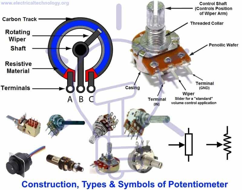
How does a Potentiometer work?
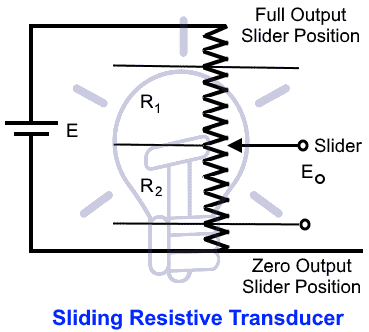
Potentiometer is a passive component that works on moving the slider across the full length of the conductor. The input supply voltage is applied to the entire length of the resistor. The output voltage is measured as voltage drop between fixed and movable contact as seen in the figure below. The slider is adjusted manually over the resistive strip to change the resistance value from zero to a higher value. When the resistance changes, the current flowing through circuit changes. Hence according to Ohm’s law, the resistive material also changes.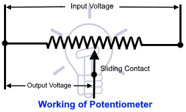
Assume that two batteries are connected in parallel through galvanometer. Negative ends of both batteries are connected together and similarly both positive ends are connected together. Since both batteries carry same electric potential, there will be no current flowing through galvanometer and its does not show deflection. The pot also works on the same phenomenon.
- Related Post: Rain Alarm Sensor– Snow, Water and Rain Detector Project
Types of Potentiometers:
- Rotary Potentiometer
- Linear Potentiometer
Rotary Potentiometer:
Adjustable supply voltage can be obtained using rotary potentiometer. A familiar example is volume controller of a radio transistor, in which the amplifier supply is supported by the rotary knob of the pot. The other applications are it is used when the end user needs smooth voltage control.
Linear Potentiometer:
It works same as the rotary potentiometer but the only difference is slider moves linearly on the resistor. The resistor ends are connected across the supply voltage. The two ends of the output circuit are connected to the sliding terminal and resistor terminal
Applications of Potentiometers:
- Potentiometer as a Voltage Divider:
- Audio Control
- Television
- Transducers
- Pots as measuring devices:
- Pots as tuners and calibrators
- To compare the emf of a battery cell with a standard cell
- To measure the internal resistance of a battery cell
- To measure the voltage across a branch of a given circuit
Strain Gauges
What is stress & strain?
When a force is applied on a material, internal pressure of the material is measured and that is called stress. Due to the internal pressure, there will be deformation of shape. Stress is given as change in force per unit area.
Strain occurs due to stress. Due to the stress applied, the material will be elongated or compressed. So, strain is defined as ratio of change in length produced due to force to the original length of the material.
Working Principle of a Strain Gauge:
A strain gauge is a sensor, which results in change of resistance due to the applied force. The parameters like force, pressure, etc. are converted into measureable electrical resistance. To a stationary object, when external forces are applied, it results in stress and strain. So here, stress is defined as internal resistance of the object and strain is given as displacement and deformation. If L1 is the initial length of the conductor and L2 is the length of the conductor after application of force.
ε = (L2 – L1) / L1
When a stress is applied to the conductor, length and area of the conductor changes, due to which resistance also changes. Another parameter which is changed is the resistivity of the conductor. So there is a property called as Piezo-resistive Effect, which tells about change in electrical resistivity due to the applied strain. Hence strain gauges are also called as piezoresistive gauges.